
Support:
PSU Interference Hardware Fix
Certain PSU's or adjacent modules that have a lot of digital noise
emission may cause low level noise in the Reflex LiveLoop
during Record operations, This adds to the low bit dithering and causes 2 or 3
bits to be involved. As a result there will be a low
level whine or buzz. In most applications, this may go unnoticed, but it depends
on PSU interference levels etc.
One possible solution is to move the Reflex to a location where there
is less RF noise. The other is to do a hardware filter
modification as described below.
If you are able to solder, and have a steady hand, this fix is for you!
There are 2 hardware modifications.
The first, the PSU mod, involving adding two capacitors to an easily
accessible 4 pads, will vastly reduce PSU noise.
The second, involving a single capacitor and a bit trickier solder connection,
will remove any dither beyond single bit,
(the random noise, or fine "static" clicks you can hear if levels on you monitor
are turned way up)
If you are accustomed to SMD soldering, then SMD components can be
used (second image below) if not, then through-hole
components can be used, (lowest image below)
Preparation:
Parts:
PSU Filter Mod: 2 x 220pF or 470pF capacitors (SMD 603 to 1206 size, or through
hole ceramic type)
Dither Mod: One ceramic capacitor 0.1uF to 1.0uF in value. (SMD 603 to
1206, or through hole)
Remove the digital board (the small board with 10 pin headers on each end) noting it's orientation arrows.
Turn the board with the 30 pin expansion header towards you so matches the photos. Orient as comfortable for soldering.
If doing the dither modification (with either SMD or through-hole components), carefully dab some solder onto 4560 chip's pin 8.
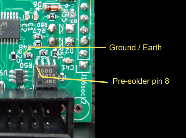
If you will be using 603 SMD components only, dab some solder on to R50 (ground/earth), otherwise leave R50 alone.
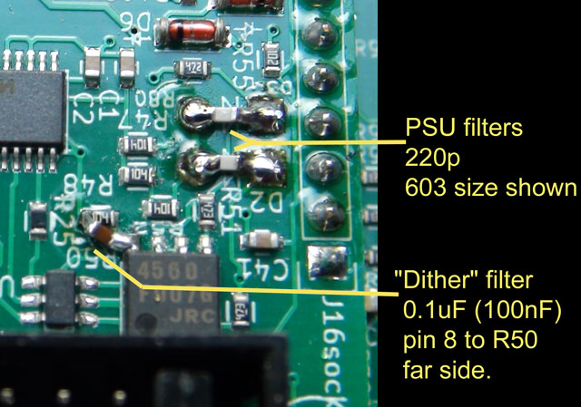
SMD (603) Modification
Using 603 size SMD's should look as shown below.
Bridge D2 and D3 with 220pF capacitors (ceramic type, white colored in picture, but can be orange etc)
Hold the 0.1uF capacitor to pin 8 first and solder while dragging over toward far end of R50. Then solder to R50.
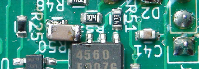
*1206 SMD's can be used for the 220pF caps, but the Dither mod is difficult
with a 1206 as shown below, so it may be best to
use a regular through-hole for the Dither (see Though-Hole mod). Depends
on your experience soldering.
Through-Hole Parts Modification:
If you're no good with SMD's both mods can be done with standard through-hole parts as shown below.
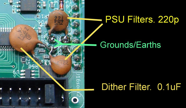
The anode sides of the through-hole diodes are both on the ground plane. All
3 capacitors can connect to them.
*Try to use a capacitor with thin leads so there isn't excess strain on pin 8 of
the 4560 SOIC chip, the ones I used are horribly thick!
*Be careful not to accidentally solder to R50 (shown under leg of added 104
capacitor) when attaching to pin 8.
As mentioned, 220pF to 470pF can be used, but no higher please! 100pF was tested with no ill affects, if in a pinch.
-----------------------------------------------------------------------------------------------------------------------------------------------------------------------------------
Note: A second modification is
here. This involves 2*22pF caps, and will
remove any input noise/interference and is recommended.
-----------------------------------------------------------------------------------------------------------------------------------------------------------------------------------
Designer's Note:
As this issue only came to light a couple of days ago (June 12th),
many Reflex LiveLoops may have a PSU compatability problem, and, while
this modification may not remove all noise from all PSU's that are in very close
proximity, it greatly reduces the noise and makes the
audio much better in general in a noisy environment. RLL's shipped after June
14th will already have both modifications.
So if you're happy with the Reflex as is (not all PSU's/layouts will
exhibit strong noise) then don't bother risking this modification, but if
you think it could be better, then go ahead with it.
For those who can't solder at all:
Shielding the offending source with insulated copper tape or insulated aluminum foil then connecting to a ground (rail, case, panel) will help.
Sometimes (at least it worked here) putting a sheet of aluminum under the
location of either the Reflex or the offending noise maker and
connecting it to the rail or a ground will eliminate the RF interference.
Return for in-house modification:
As a last resort, we are accepting digital board returns. If you are in the
US, or somewhere you won't get heavily taxed on parts
coming into the country, then you can detach the digital board (the smallest one
as is photos), wrap it in some bubble wrap and stuff
it into a CD type of envelope and send it letter mail marked "warranty parts
return" or similar. It's light and won't cost much to send.
We will do the modification, and pay for return postage to you.
*Note: If there are taxes/duty owing when we receive the package, we will not accept it, so label envelope to avoid this please!
We Sincerely apologize for this oversight and wish you all the best with your Reflex LiveLoop experience!
Sandy Sims & Gena Hollingshead
SDS Digital