| A RockBand Drumset to MIDI Hardware Hack! | ||
|
|
by Sandy Sims
|
Back
in the "old" days, I had a real set of drums, some Diamonds, and used to
play almost daily. But as time went on, the opportunity to play them became
less and less. Mostly the TV (i.e. others watching it) and the internet (in
close proximity to the "drum/dining" room! ) were to blame. So I purchased a $1000 Roland set, but, as usual, the box had been opened and the wrong power supply had been put in there (AC vs. DC) and there was so much trouble returning the thing, I just gave up on the whole idea. Later on, I decided to build a table-top unit with 8 pads, which was made of heavy iron and it worked great even though there was some cross-talk between the pads. When we moved onto the boat, it was just too heavy and dangerous, so I gutted it for the electronics and stuffed it all into a zip lock bag, and there it sits.
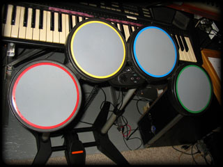
When
we sailed into the US, I saw one of those RockBand toy drum sets. It seemed
solid enough so now there's one sitting in the studio. I managed to figure
out a way to interface it with the PC, as it's recognized as a joystick. I
found a nifty little proggie that converts joystick buttons to alpha-numeric
keyboard characters, which, in turn, my DAW software (FLstudio in this case)
can turn into notes on the synth, sample, or MIDI out in focus. There is
very little latency, well except with the "kick" pedal, which is an issue I
plan to address.
The
ultimate solution isn't to drop a couple Large on a new set of V-drums, but
to do another fun electronics project! Disclaimers: I
will make this, the schematic, and the firmware, public domain
so anyone can have a go at it. So I assume no responsibility on whatever
goes wrong with yours! ..Of course, once I set my sights on something, it generally becomes mine, either by building it myself, or nice people feeling sorry for me and giving me one :)
|
|||||
|
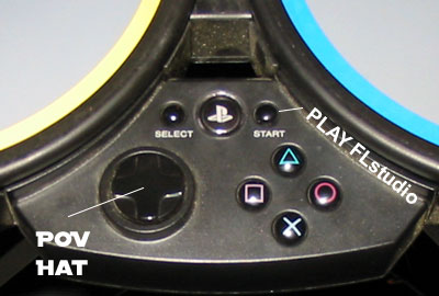
The
Rockband(tm) drums have a little control panel in the center (photo right)
which I also plan on hacking, into a PIC 16F57 micro-controller. I chose the
'57 not because they are MIDI-ready, or even have a USART, but because I
have tons of them (C57's) left over from the 16 knob thingies. These buttons will control stuff in FLstudio, as well as programming note# - drum pad data. The big red button could be used to turn MIDI note output on/off, so it can still output MIDI CC data for controlling other things...
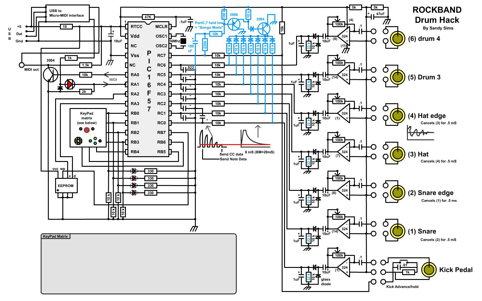
The
first step is to draw up a schematic to see how feasible it all is. Here it
is below. The big empty box is the keypad configuration, and, well I haven't decided how to configure it yet! It may have been written into the completed schematic by now, so click the image to open in a new window.
|
 |
||||
|
|||||
| This
pulse of voltage is measured, then translated into MIDI note velocity, and
tacked on to the end of a note that corresponds to the pad being hit. After
the voltage drops below the PIC's input high threshold, a second piece of
data has been recorded: the time it took to discharge. This will give a more
accurate reading of the velocity, but would take to long and might create
10-20 mS of latency, which is a no-no on any DAW!
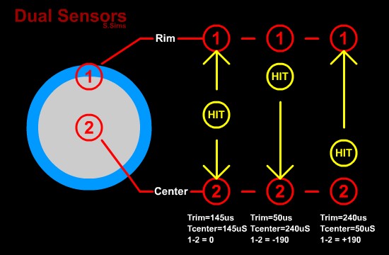
I hate wasting perfectly good data, so this could be used to send a MIDI CC value (control change) which could be used to control a cut-off filter, or perhaps even the level of a sample. It gets even cooler! You may have noticed some of the drums have 2 sensors? The theory here is based on the speed of sound, or shockwave thereof. When I hit the rim of a snare, I want a rim-shot sound not a snare! So a second sensor somehow attached to the rim area or even close, will produce good results. I mentioned
cross-talk from one pad to the other in the table-top drumpads I built
before. There was a few hundred microseconds delay from one to the other, so
I was able to cancel the resulting echo of other drum parts in software.
This didn't always work well, especially if I was trying to simultaneously
hit the pad that was being cancelled. Ugg! Another interesting dual sensor would be for the kick. The stock kick is just a magnet and a reed switch to sense it. I good idea if precision isn't a consideration. I am putting a piezo into it, but have decided to keep the switch as well. The switch could be used to measure velocity and provide CC data, but also it can be held longer to act as a muffle, just like a real kick. I really hate the action on this pedal though, having used a real pedal for years, so that may have to be modified to resemble a real action. A spring that flops over? a replica of a real kick pedal?
|
 |
||||
|
There
is an EEPROM on the schematic, which will keep track of all the note -
drumpad settings that I'll be programming in. Because there are only going
to be 4 LED's ( One for each Pad, all 4 for the kick ) to select pads to
program, the number of "memories" should be 16 ( 2^4 ). Beyond that, using a
track in FLstudio to program the Note-Pad configuration as soon as the song
starts, could act to facilitate a more universal method of setup. Maybe I'll
write a PC software for flash-MIDI to load/save data like a standard MIDI
controller board. Well getting ahead of myself, I haven't even started to pull the thing apart yet! On the subject of MIDI interfacing; I am fresh out of midi sockets to plug this in to, so I'm going to fork over $40 and buy one of those tiny USB-MIDI interfaces, then built it in. That way the nice long USB cord that comes with the Rockband drums can still be used. Plus the whole thing can be run off of the 5 volt USB power, no more adapters, yay! |
|
I will add updates to
this page as the project moves along. It's halfway through Nov.2011 so maybe
I'll have a start on it before Xmas. I just have 2 other "more important"
projects to do first. Sandy NOTE: This project has been cancelled in lieu of a Yamaha DD-65! Oh well! |
DrumpadzVST - flp's - schematic - PC Board - PIC .asm - dp_project.zip - Digikey
![]()