| SDS KeyPadz | ||
|
|
||
|
During the past
year or so, I've been doing a lot of performing and even though the shows
went smoothly, I've heard some complaints that there's too much of a "gap"
between some songs. If I'm performing without any accompaniment, then I can almost flow from one song to another, but if a song needs the MIDI sequencing from the computer, then I find I'm squinting at a screen (especially if it's outside with sun shining brightly on the screen) and trying to maneuver the touch-pad style mouse arrow to the next file. As they say, necessity is the mother of invention, and something needed to be done about this. I have researched using a keypad to trigger macros but couldn't find a reliable way to have a numeric entry from a standard USB number pad. It would converse with "hotkeys" in my sequencer program and do all sorts of weird things depending on which window was "on top". After some
searching around, I thought I had found a macro program to fit the bill,
only to discover it was almost $300, and with the limited "it can do this
and that" info on the site, I wasn't about to fork over that kind of cash if
they had no demo to test. So after some more searching a few days later I
found the FREE program "AutoHotKey".
It is script based, and can do virtually Now all I
need to do is find a keypad. I researched gamer keypads because they are
robust and usually have some form of mounting hardware. They are
programmable, but as I soon discovered, |
|
|
I
want to be able to:
- type in a 3 digit song
code (from my songbook or memory) and have it open the MIDI sequencer
program if not already open, - Have clearly defined Play/Pause & Stop Buttons - Have a pedal switch that controls Play/Pause - Be able to set the next song from the key pad and arm the pedal switch to load it when pedal pressed. - See / feel the keys in the dark, so a large old telephone keypad will do. ( Thanks June for all the old phones! ) I thought
to myself, " why stop here? ". It's a big secret right now, but sometime in
2013 I will be performing a show with |
 |
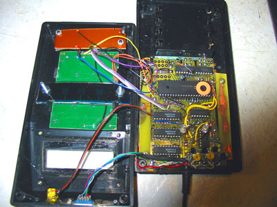
| I
started studying up on PS/2 keyboard/mouse protocols when I found a game
controller at the used/economy store in town. It's USB, but no "real"
joystick, just arrows. The reason I bought it was lots of round buttons ( which I like because one only need drill a hole to put one in a panel. ) Including it's "fire" buttons, there's 8 buttons plus 4 axis buttons. Why use a game controller? Because, even with an advanced HotKey program, keyboard keys can be a real pain in the butt if outside of the intended application. Every contingency must be considered. Some programs "steal" the hotkeys, which isn't a problem with output from AutoHotkeys, but the input keys trigger other things, and windows dislikes being cooperative. With a game controller, none of that is an issue!...well unless one likes playing games on one screen while composing music on the other lol!
|
|
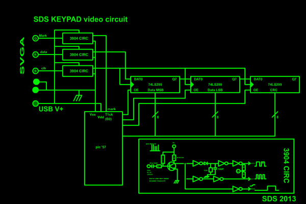
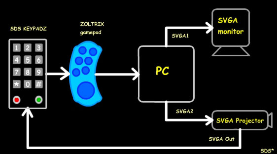
| This is
how everything will connect once the project is done. The game controller
is actually inside the SDS KeyPadz unit, but I showed it for clarity. The Video Codes: I
am lucky enough to have a BenQ MS510 projector which has an SVGA output
that sends exactly what
|
 |
||||
|
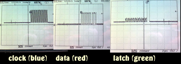
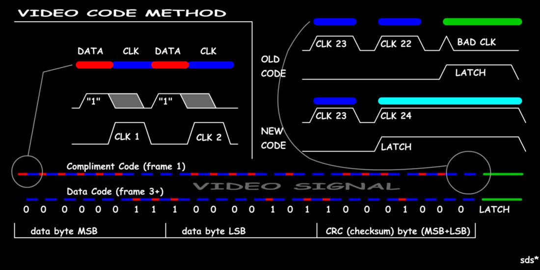
The video "code" is just 2 8-bit bytes, followed by a CRC or checksum
byte. This means there will need to be 24 clock pulses, and an end pulse
(green) to latch them into a microcontroller.
Because of the
way different media players and Codecs handle colors, I was unable to just
overlap each color, i.e. blue/violet = blue and red, so I had to make the
clock and data pulse |
|||||
|
|
Using a simple delay capacitor between two 7414 invertors is an easy fix!
(Diagram, left)
If you plan on building this as well, don't worry, I'll do up some better schematics when I have some time. So, before moving on the the simple keypad section, in a nutshell here's how the video signal and code looks /works... |
||||
|
The bars near the bottom are pretty close to what the video image actually
looks like.
You
may have noticed there are two bars? After playing around with the code
and adding a CRC, which is the last 8 bits of the sum of the first 2
bytes, I thought it's be secure enough.
It's rock solid and hasn't monkeyed up yet.....well that way. Now there's
a problem with getting the proper data. I noticed that video converted (to
WMV in this case) and played back
After doing some "demo" videos, which start up FL Studio, and start
playing a song part way through, then stopping it again, I have found
those code bars at the bottom aren't even
The Key Pad Circuit: |
|||||
|
As
I mentioned above, I've decided to use a telephone keypad. Mostly because
I'm very familiar with it, whereas the type on the right of a computer
keyboard is alien to me. I can use a telephone in the dark, which I have
done lots in dingy back hallways of bars and at night in dark payphones
with burned out lights etc. When on the stage, sometimes the actual
performance is all you want to think about, so anything the adds to the
simplicity is a bonus.
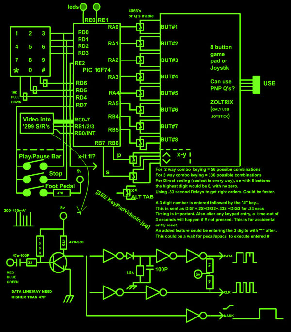
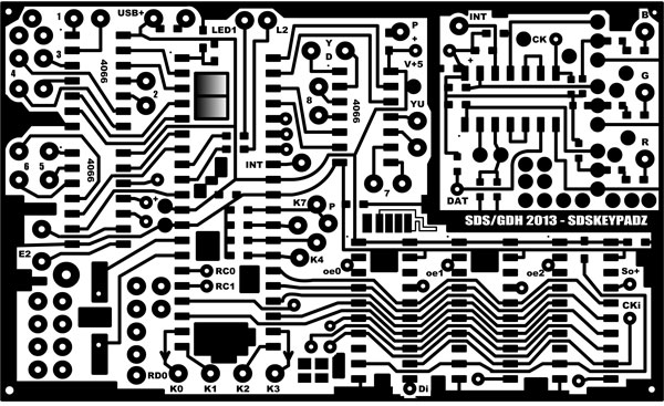
These keypads
are all standard 3x4 layout, so the PIC 16F74 only needs to pull up each
row The foot pedal can't be scanned this way as the long wire would create too much capacitance and may trigger a Play/Pause at the wrong time, so better safe than sorry. Before each keypad scan, Port D,7 is checked for a high level. If it is high before the scan has started then foot pedal has been pressed. The outputs on port A & B are driving a 4066 quad analogue switch to "press" the game controllers buttons. I could have used transistors with this controller, but if it ever fails, who knows what might be next, so once again, for the little extra board real estate it's worth it. Each pair from the 4066 is isolated away from ground/Vdd which is a good thing as some of the keys were positive & others neg. The board to the
right is mostly accurate, except the added 75 ohm resistors to ground at
SVGA inputs B, G, & R. ...and a 100k pot to ground from the base of each Q
to control the bias/gain levels. |
 |
||||
|
On this game controller is a 4 way thing that looks like a POV hat, but
it's not a POV, it's actually an X-Y axis that is simulated to act like a
POV but control an X-Y! That'd suck for most racing/flying/shooting games
I've ever seen, which is probably why it was at the economy store for $2
lol! If you are going to build this thing, a proper joystick would be
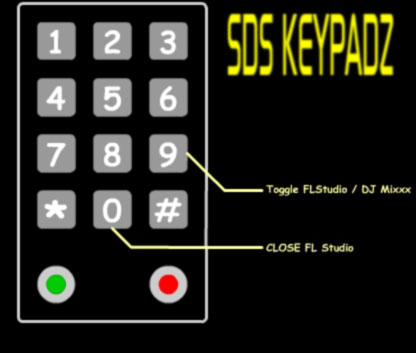
best, then just hook the Y axis <10 to Port B,6's 4066, & Y axis >60 to Port B,7's 4066. ( X-axis < 10 is on Port E,2's 4066 switch) Because the game controller only had 8 buttons, I decided to only involve the numbers 1-8. This may have been a silly thing to do, but it's done so no going back hehe. The 2 remaining # keys close FL Studio (#0) and toggle between FL Studio and DJ Mixxx (#9) like <ALT> <TAB> does, except just between those 2. You could change the AutoHotKey script to anything though.
|
|||||
|
|||||
VIDEO
|
|
|
Well, that's
about it! I hope you could understand a least some of this, and to anyone
that wants to build this thing, it'll be a lot clearer with proper
schematics. It's all that I'd hoped for, and I'm having so much fun with it. I've already added codes for most of my songs, but also added some to open up Sony Acid and add a recording track and start recording the 2 main channels off the mixer. Perfect for jamming so I don't have to stop and monkey with the PC for 2 minutes. I have some other ideas too. PC's should come with this! If you don't want to build stuff like this, but still like macros the make life in 'puter world so much easier and save tons of time, check out AutoHotKey, it's free & easy to use! I hope you enjoyed the article! Cheers! Sandrine Sims *
|
|
Disclaimer: This is not an
instructional page to build or manufacture the above project, nor are there
any guarantees of accuracy herein. This page is an "of interest" discussion, and the project is intended for my own personal use. If you have any questions, or wish to pursue this project, you may contact me (Sandra) at fresh(at)freshnelly.com |
![]()