| Notice
the display is white? That's because it's an OLED display. It's pretty tiny,
about the same size as a small LED 2 digit display, but it's bright, and can
do all characters and graphics, even animations! That will be fun during
setup, but can still show the big digits for a performance.
Last but not
least, there's now 3 MIDI outs on the panel, there's really 4, but that's
exclusive to the on-board
VS1053
synth board
and
MPX8 sample player (using out-of-range drum notes)
So if a real synth like my Korg or better drums etc is called for, the
sequencer can have access to them. Hey! I forgot the headphone jack yet
again on the new design :P
| Because
I order a lot of parts from China, I'm never exactly sure what I'm going
to be getting until it arrives on the doorstep. Sometimes it's not as
I'd imagined, I'm sure everyone has had that experience!
Well such was the
case with the encoder "pots". They are great quality-wise but the shafts
on then looked a bit longer in the picture on eBay.
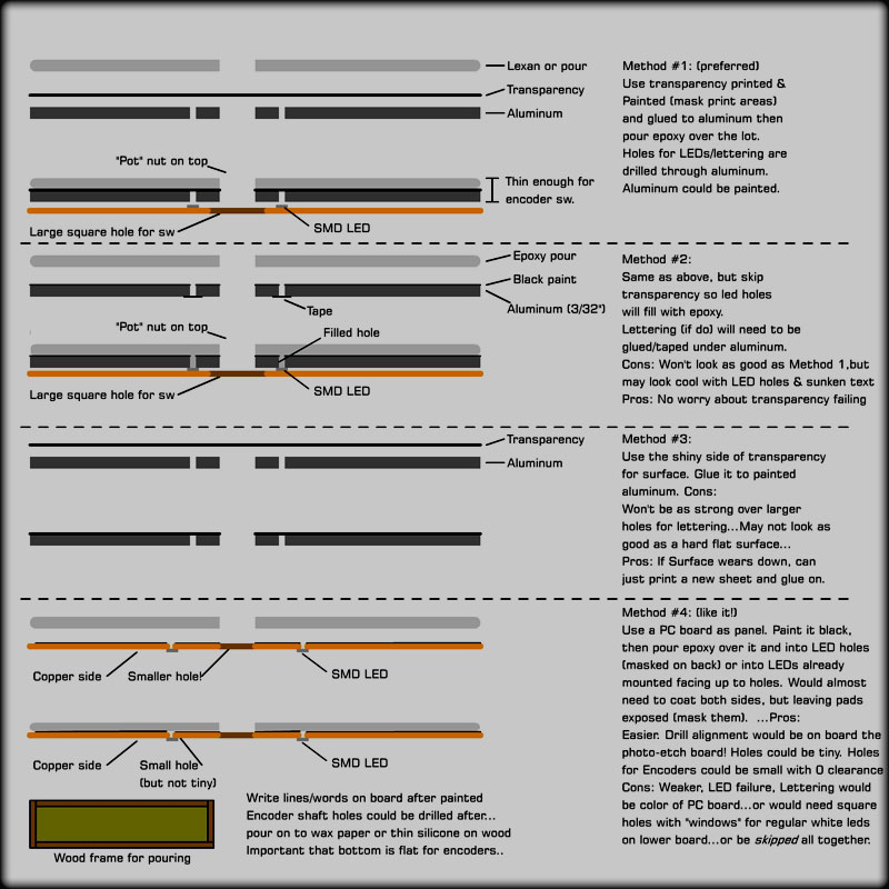
As a result, I've had to re-think the whole lexan over aluminum idea,
well at least for that part of the panel. The shafts are simply not long
enough to go though the 1/8" lexan, then into a rather deep knob, which
I also ordered at the same time.
The SMD LEDs
and the short shafts didn't work together as you can see in the
"Methods" image to the right.
I really had
my heart set on using the laser printer to make a mask for the
lettering, but it may not be so. Back to the stick-on letters or
paint-pens. I wish I had a silk-screen setup, but unless I was going
into production, it'd hardly be worth it.
Method 4
is the present consensus. There's something appealing about mounting
tiny (really bright! ) white SMD LED's upside down so they poke light
through a 3/64" hole while trying not to "melt" the black paint off of
the other side of the board! Hmmm...
Well
we'll see how long this design lasts before I re-design it! Meanwhile,
I'm slowly working on each section of the unit and the design all-in-all
is starting to stabilize. |
 |
Update
May 1st 2014
The boards for the encoder panel has been designed. The rest of the
panel's size will be determined by this, then the exact size of the box
from that. |
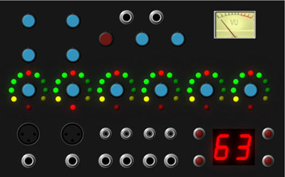
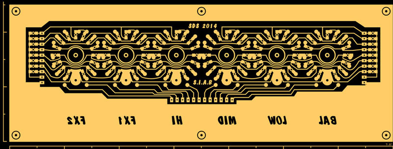
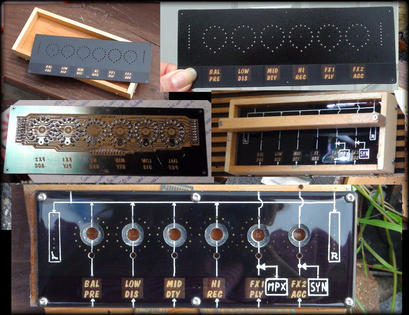
| Each
encoder has 15 white SMD LED's around it to show the position of the
"knob" that will change depending on the function of the panel at the
time.
As
mentioned above, I've made the decision to mount the tiny LEDs face down
over a 3/64" hole. So this trace side view (top board) is looking up,
that's why the lettering is backwards. The lettering will be lighted
from a small board and a diffuser glued on after the epoxy is applied.
On
each end of the board, you can see the vertical 8 LED level meters.
These will stay exclusively meters, but the LED's around the knobs will
become spectrum analyzer bars after no adjustments have been made for a
while. I have 7 bands at my disposal from the Main Output's TDA7419, so
I'll use the 6 lower. In an acoustic scenario, the 15 khz+ band is
useless anyway.
The pads
going around the knobs are commons for each set of LEDs. They can't go
through the board as the other side will be visible on the panel!
It'll be sort of like knitting with a thin wire and the soldering iron.
The hole marker under each knob is for a standard 3 mm LED that will
indicate the active Channel Strip when adjusting tone controls etc.
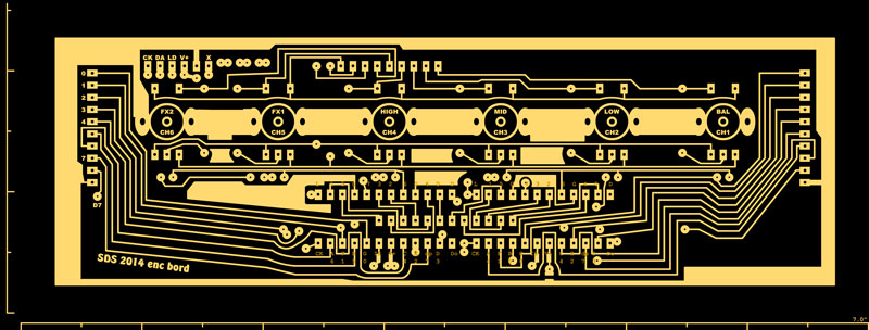
These
LEDs will be mounted off of the lower board on stand offs. Headers on
each end and in the middle will line up so it can be plugged right in.
Headers off of the panel board must be "surface mounted" as holes
shouldn't be drilled through!
The lower board is somewhat smaller so it can fit through the hole in the
aluminum part of the panel.
The
encoders will mount onto this board, hence the footprint for those, the
the nut threaded onto the top board. This means the thickness of the top
panel must be pretty accurate! These 6 nuts will be the support for the
bottom board.
2
headers lead off of the lower board to connect to the mainPIC
(Sequencer) board. These carry the encoder Up/Down/Button and common on
one header, and serial data for all of the 240 LEDs on the panel. |
 |
Luckily,
the 8x8 drivers only drive 8 LEDs at a time, so even if the 240 LEDs
were all on, the draw could only be for 16 LED's, which at normal indoor
brightness may be 40 mA or so.
The 2 two LED driver chips, are the MAX7219. These chip are over 10
years old, but have become really popular on eBay for super cheap,
probably because of the Arduino Revolution!
Completing
the panel board is a 1 shot deal that I'm a bit nervous about. It must
be drilled, masked over the lettering and painted black on the back
side, have LED's mounted, have jumpers installed, then be well tested,
all before siliconing aver the header pads and dipping it all in the
epoxy..
It's important
that the epoxy box be lightly siliconed and perfectly level as the panel
must be completely submersed at least 1mm so the drilled holes don't
create "dips" by the skinning effect.
The silicone to the epoxy is like oil to water. It shouldn't bead up on
the edges at all, in fact, I'm hoping it will angle down. That way the
edge of the panel will be easier to finish.
I'll have to do it on one of my "good days" or it'll be an unfixable
disaster! Maybe a scale test is in order with no board first...
|
Update May 18th
2014:
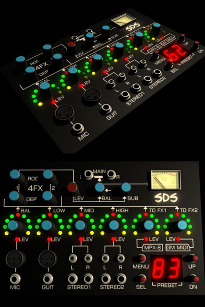
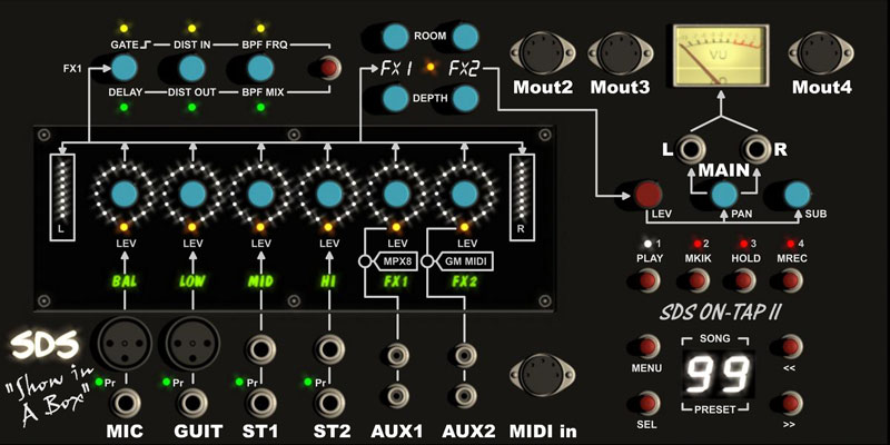
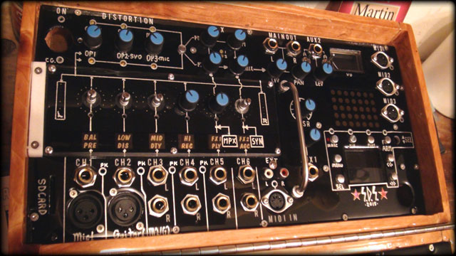
Here's the new
and more or less final layout! It's stil within the size limits and has
pretty much all of the elements required (I almost forgot the SD Card slot!)
The buttons may end up as home-made caps. I've been contemplating using the
lathe to cut out some aluminum rod and polishing the ends. These would press
against a standard PC mount button. I've printed this layout to scale and
it's very close. The 1/4" and XLR socket spacings are accurate, allowing
enough room for their cases.
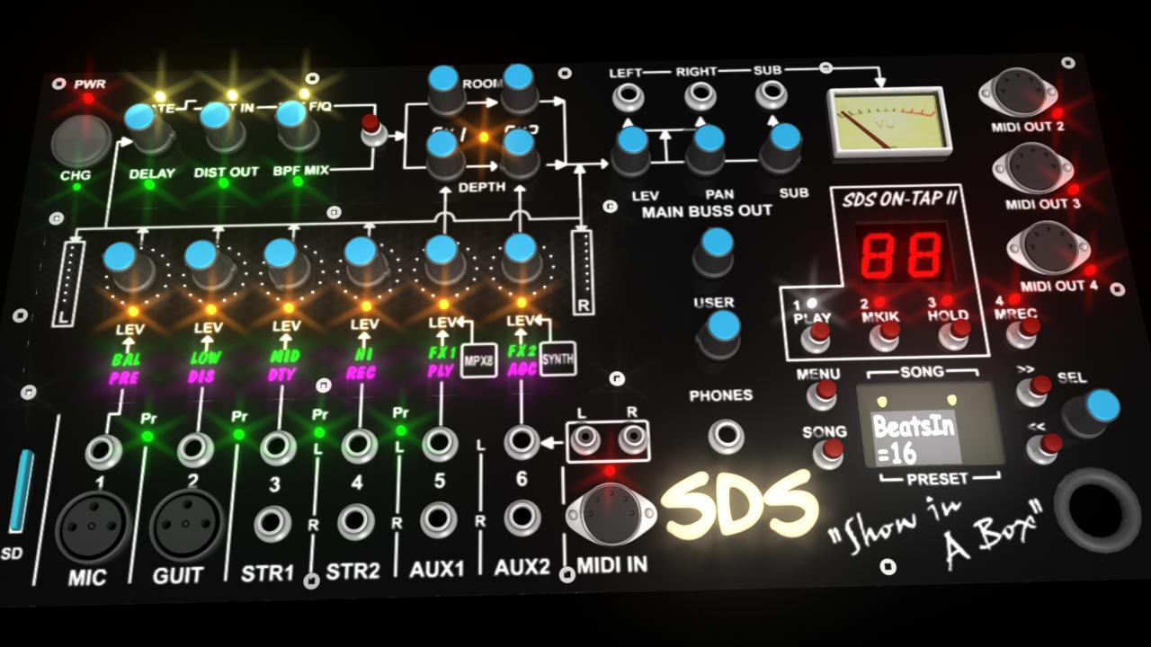
This layout is
pretty close to the one above, but once re-sizing the panel to be large
enough for the box size to accommodate the MPX-8, it looked kinda bare!
An LED display has been added for On-Tap sequencer functions. It'll count
beats, show incoming MIDI notes etc. Not sure what else. Some important
addition are the "User" knob, which can be programmed to control any
function, even a MIDI out CC, the "Phones" knob to adjust headphones level,
the phones socket, and a dedicated "SEL| encoder knob for the menu.
Originally one of the knobs on the encoder board was to take this duty, but
it seems kinda complicated that way.
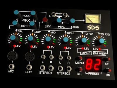
Oh! ...and the
OLED display is seated lower into the panel so a magnifier can be used. This
should make it more "viewable" (I hope!) You can see those yellow LEDs in
there, I'm not sure why I did that, but as soon as I figure out why I'll let
you know! A power switch on the panel is good, and a charge indicator. AUX 1
& 2 are now standard 1/4" sockets. These will feed to a stereo mix to share
channels with the built-in synth, and the MPX-8. Finally, the large grommet
in the lower right corner is for a curved cable tray to feed wires across
the hinge from the lower box section.
The scale is
correct for the whole thing, with real components, so I'm pretty much ready
to start cutting aluminum plate.
 |
A cool
trick I like to use for testing a scale during design (in Flash) is to
use DIP IC spacing somewhere in the layout (this one has the encoder
board which I used to scale the whole thing) and shrink it on the
computer monitor until a real DIP plug matches the spacing. With a 40
pin chip, it's pretty accurate!
Then I proceed to place the actual parts, i.e. pots, sockets, LED
display, etc., against the screen. It's amazing haw far one's
perspective is when it comes to designing something "on screen". Things
tend to end up too small.
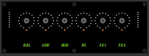
As you can
see, I've made the encoder board/panel. The PC board under the
photo-sense is completely different than what I'm accustomed to. Instead
of translucent green, it's nearly opaque yellow!!
This board is so opaque that I couldn't tell it had finished etching
while copper side down! Very unusual for MG chemicals.
Anyway,
I've worked around it by utilizing some 5050 SMD LEDs to light the
lettering (which now shows a third function!), put the original
transparency over it, and taped it on to sharpen them up. I found that
red/green (yellow) is great, red or green by itself is also nice, but
blue is almost not noticeable at all. Blue with red makes a crimson kind
of color though, so I will use it. ( RGB board not shown )
After
soldering on the 106 white "pixel" LEDS, and testing them all, it was
time to place the board in the epoxy box. Screws were used where each
encoder hole will be drilled, mainly to make sure the board was flat. I
must admit I was very nervous about doing this because any damage to the
board would be extremely hard to fix with 1/8" of very hard epoxy over
it!
As you
can see, it came out not bad. My sloppy hand-drawn paint pen graphics
aren't as good as the CG photo above, but it'll do. One disappointment I
did have is some of the LED holes ended up with bubbles stuck inside
them. Had I noticed this I would have popped them with a pin before the
epoxy hardened. Yo can see which ones (there are many) have
bubbles as they're not as bright. The first circle is perfect. |
 |
It does affect the low level LED brightness, but when bright not so
much. The bubbles are acting like little lenses that reflect the light
outwards, into the side of the hole. Oh well, live and learn! The total
thickness was of course too much for those bloody encoder shafts, as
predicted, so I went with the contingency plan and routed them down
using a dremel.
One final kinda disappointment was the edges didn't run down as
predicted, they went up. They had to be cut down. If I had to do this
again, I would make the box oversized and cut it out. That way the edges
would be relatively flat. I managed to "dig" out the contact points and
connect headers. The LEDs all work! Yay!!
I'll post some
more pics once I've finished populating the lower board. All in all I'm
happy with it, it's tough and panel-ready! |
Until Next
time! Cheers, from Sandy
June 4th 2015
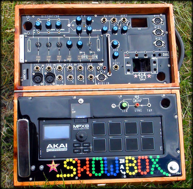
The box looks finished! Well almost! I know it's taken a while, but this
is one huge project, much bigger than I ever thought. Anyway, over
winter I designed and built the embedded synth, the distortionPIC board,
the Sampler, and the Power Supply.
The panel was done
to take a break from the design of the other 14 boards that need to go
into the SIAB. . . and here it is! Amazingly it looks pretty close to
the CG rendition.>>>
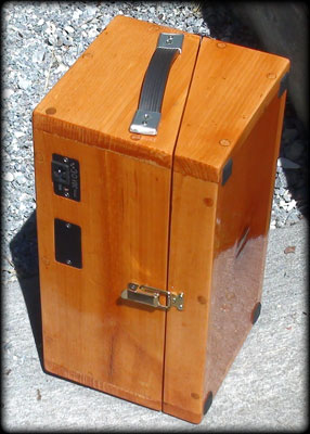
The back
of the aluminum panel had to be gouged thinner for the 1/4" sockets as
they have almost no thread on them. The extra thickness of the pour-on
epoxy made this absolutely necessary.
I decided to
glue on the tinted bezel (over the 7x5 LED matrix) before pouring. This
has made a great finish with an almost concave lens effect. You can see
that better in the unfinished image below.
The SD
Card slot had to be cut before the epoxy completely set as it gets
really really hard once finished (about 24 hours). The minor holes (up
to .5") were backed with tape then drilled after as their edges won't be
seen under nuts and knobs.
The
larger holes, for the meter, LCD, MPX-8, and wire feed-through, were
allowed to drip through, giving them a nice soft edge. |
 |
The
button holes had to be carefully drilled (slightly over-sized) so not to
damage the visible edges. everything else went in as expected. Some of
the lettering I drew by hand, and others, the CH1,2 etc, were stick-on's
I found at the dollar store. They were bright white, but the epoxy
must've soaked into them a bit and made them darker. It was
unintentional, but they look better and closer in colour to the silver
lines I drew on. The hand-spun aluminum buttons I made also match so
great! |
|
In this photo it
looks rather odd because the sky is reflecting off of the reflective
epoxy finish. It's a bit of a pain to pour, but the finish is very
tough. Minor scratches will actually fix themselves as it's always
mildly fluid, or so I have found with my guitar.
Last but
not least, the somewhat "tacky" words "Show in a Box" was with
carvnivals in mind, you know, the chaser lights.. well whatever, I like
it!
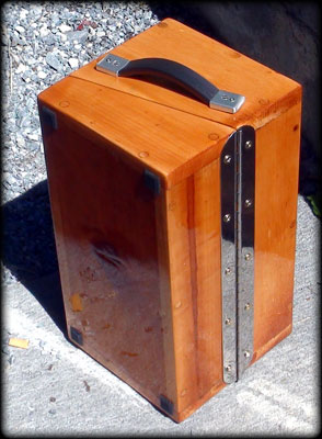
The case
closed is an unassuming wooden box. only the power socket and
programming access panels give it away. I'm sure I'll be asked to shine
shoes!
|
 |
Well that's
pretty much it for the panel(s). I'll post some dark room shots/video once
all the lights are blinking and the LCD display is in. (That'll be a while,
Dec 2015?)
Cheers, Sandy *
 to
The Audio Setup
to
The Audio Setup |