|
Variometer Project by Sandy Sims |
||
 |
||
|
Variometer Project by Sandy Sims |
||
|
|
||
The Variometer is something used
in flight, in my case for paragliding!
It tells the status of your altitude. Not the altitude itself but whether
it is increasing or decreasing by tones beeping in correspondence to
how fast you are rising (or sinking)
|
Yep! You read it right! Sandy is getting
into paragliding! I've always wanted to fly for recreation, fun, and inspiration with music and life, and what can be more inspiring than personal flight? Originally it was going to be hovering on many drone motors, then a rotating wing with fewer larger props (that may still happen!), then hang gliding, now it's paragliding and I already have a wing and harness so here I am. One of the most useful pieces of kit to have up there is a Variometer. This is to indicate whether you are coming into a thermal or updraft so you can take advantage of it. This is of course only when you're up there as opposed to beach skimming and riding bluffs where you're close enough to the ground to see if you're going up or down. At higher altitudes, above 100 feet it starts to become difficult to tell and combined with swinging and turning almost impossible. |
|
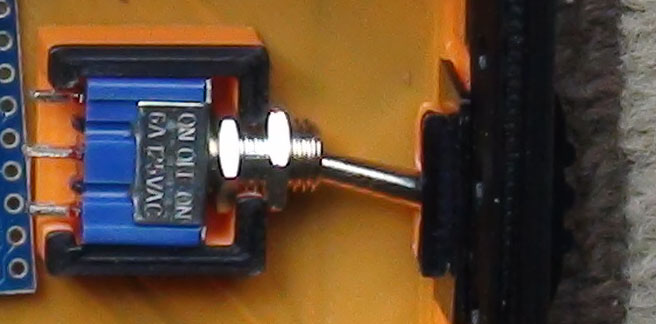
Variometers can be purchased for $100 or $200 for a nice one, but I have decided to build my own as I want the tones to be musical, (again, of course!) not just annoying beeps. The Basic Circuit So, I've ordered some parts to do the job. The primary board is a BME280 Barometer-temperature-humidity sensor obtained for a couple of bucks from Aliexpress (which is what I'm still waiting for) a couple of bidirectional level shifters (The EEPROM will probably have one too) to go from the 5V arduino to 3.3V and back, a Pro-mini AT328 oddball wherever I bought those last year, and a CH341 (or CH340T) to get serial for programming and data dumping to USB. There's also a piezo beeper to emit the beeping sound and a couple of transistors in a push-pull configuraion in case I decide to go with a speaker instead. The "Set" button may be used to start recording/stop recording or to set the launch point altitude relatively. The pot is for audio level and will be adjusted only when the box is open. The three LED's are for power, up & down. The Up & down will be bright but probably useless unless flying near / after sundown. (which is highly unlikely at this juncture in my level of experience) The power comes from a 9V battery, and while I know arduino's aren't the most power conscious boards on the market it should be good for many hours or recording... we'll see!
|
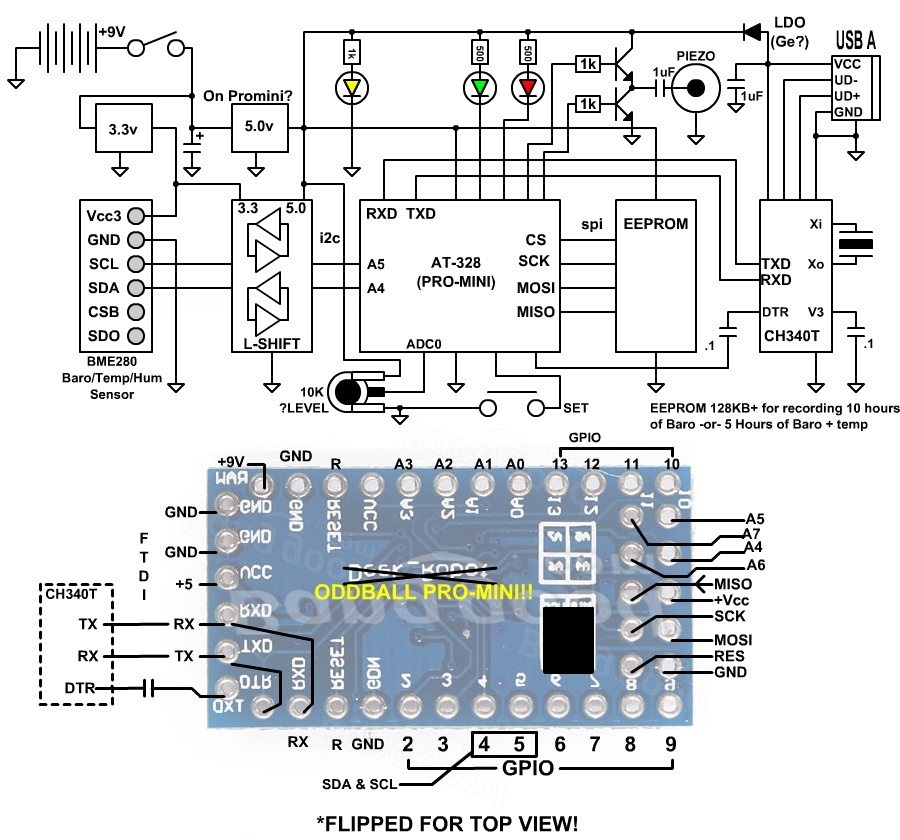 |
| EEPROM: I want to be able to record altitudes and possibly temperature for downloading & analysis back at home. This will require a substantial non-volatile memory. The EEPROM will have to be at least 2Mbit bit probably the 8Mbit flash style AT25DF081A will be used because I'm sure I have some already (strip-light & light-bar used them) and there will be many hours of recording capability if done by the second: 8,388,608/32 bits=262,144 samples = 72 hours
Tweets: Case Design: |
|
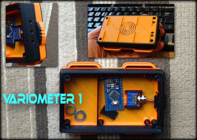
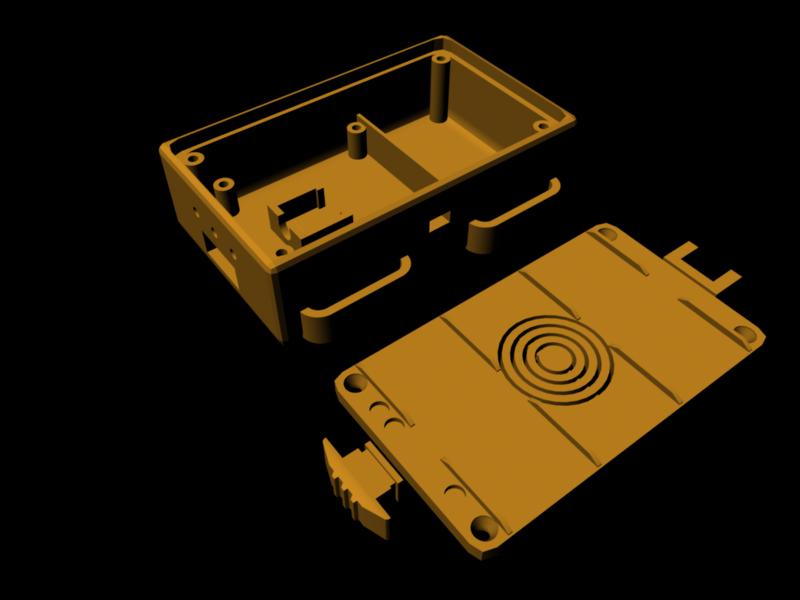
| Once again I am visiting the 3D printer
room (guest room hehe) to print yet another plastic creation. Let me tell
you, this has been the single most useful tool I have ever owned and it
gets a LOT of use around here. barely a week has gone by since 18 months
ago that I haven't used it to print up something! I couldn't live without
it. Anyway, the case must be designed in a way that it is small enough to attach to the harness or paramotor frame (another story for a future project!) in a way that is strong. As can be seen in the title image, there are two sets of slots to accept 1" velcro straps that will wrap around the box, hence the guides in the lid.
|
 |
||||
|
|
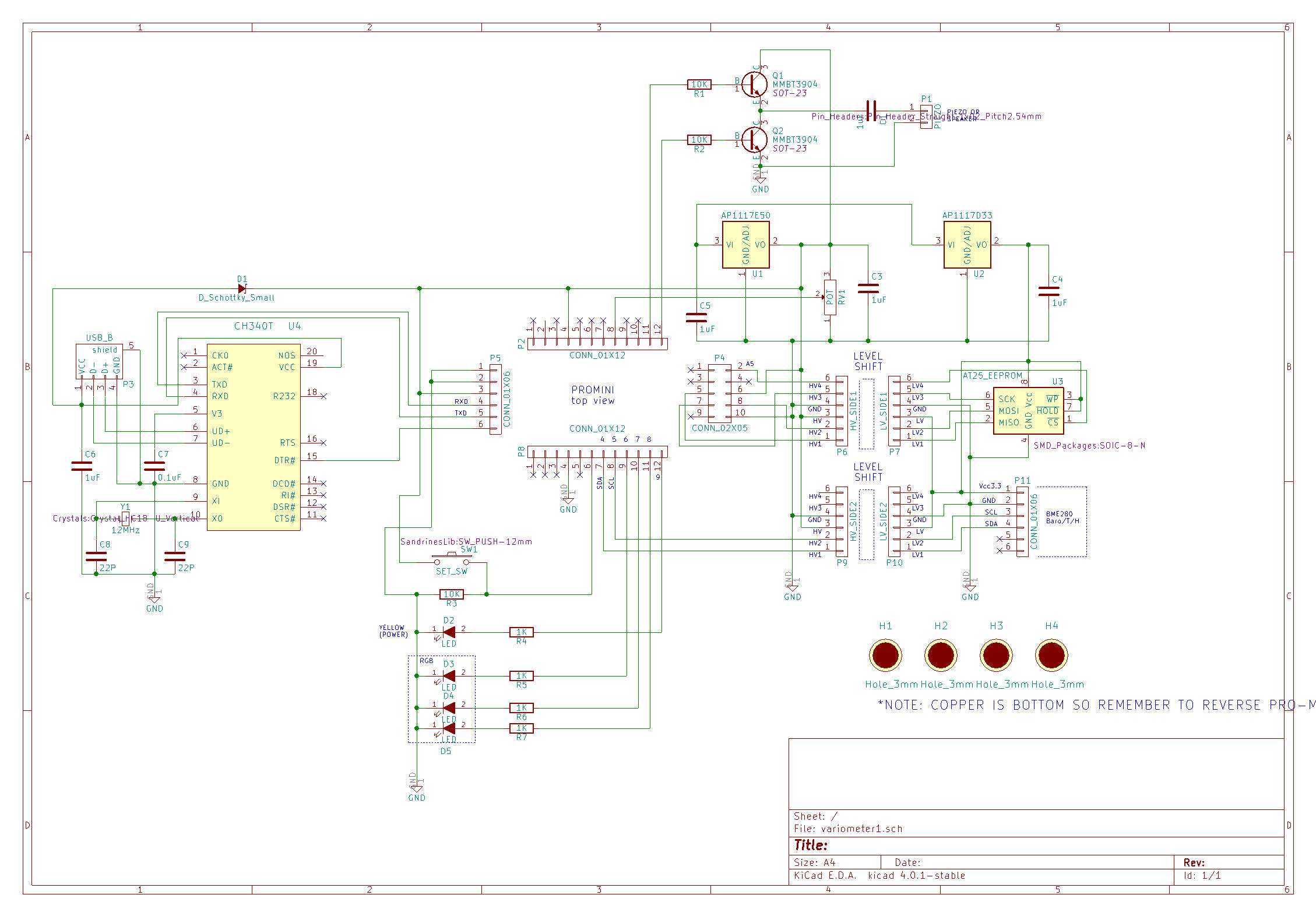
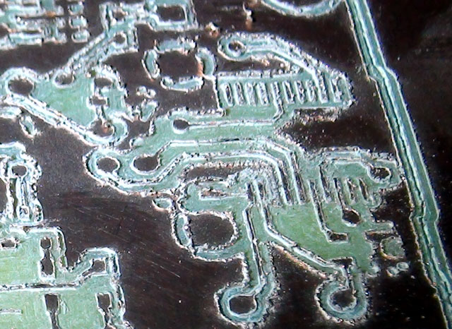
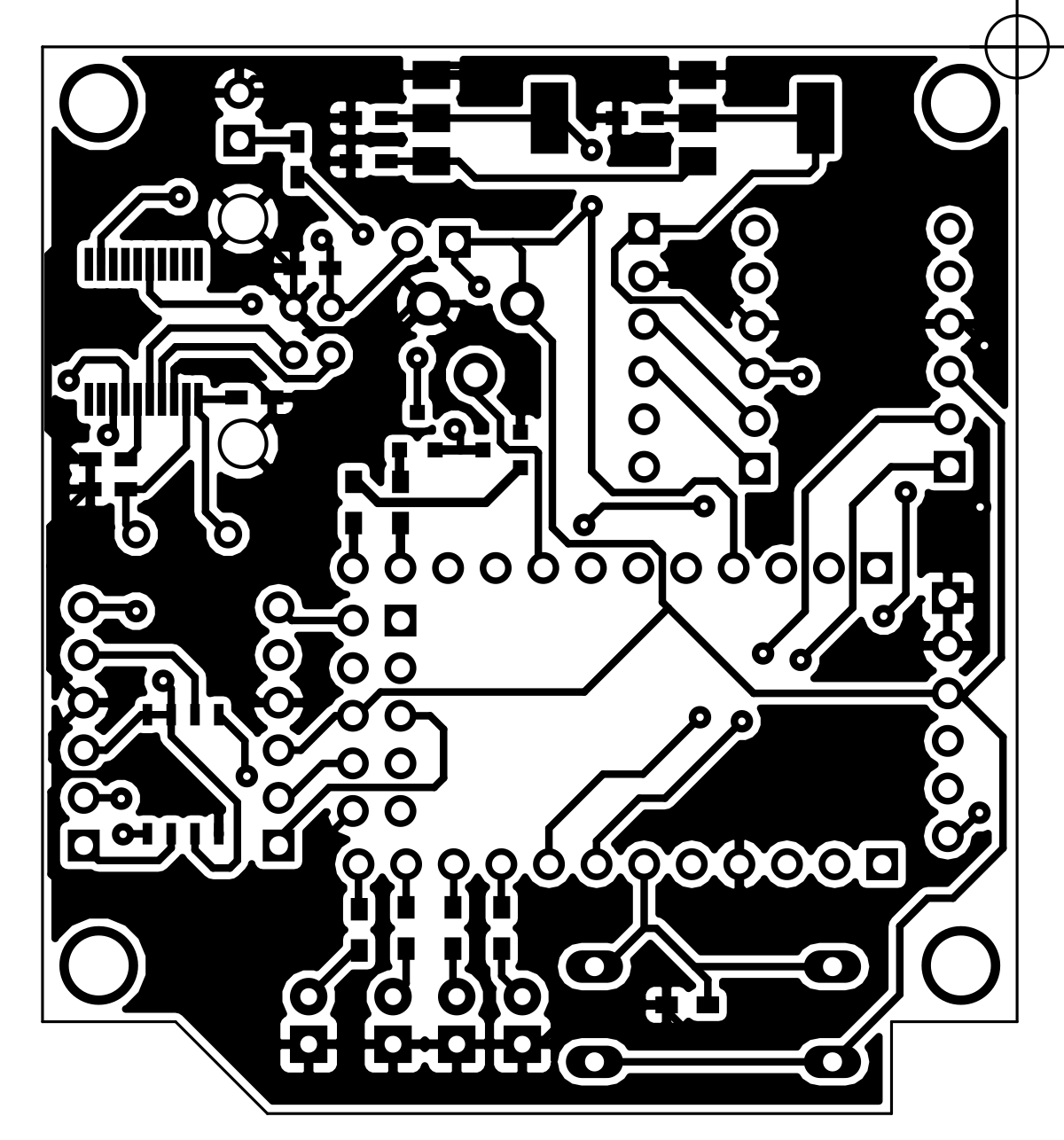
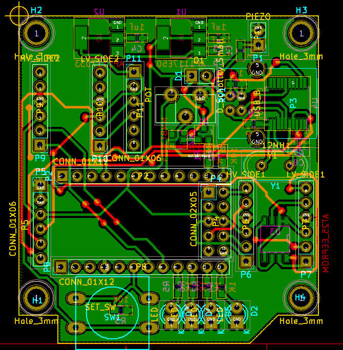
May21st 2018: I finally finished the KiCad design for the PCB. The schematic (right) can be expanded in another window. I tried using the CNC router to do the PCB but it's not very pretty so I think I'll go over to photo-sensitive PCB and etching as usual. The main problem was the .65mm pitch CH341 USB chip which is kind of sketchy copper peaks on fairly deep valleys.
This was a fast cut after I discovered the board was inverted! |
||||
| Oh well! CNC is good for alignment and
drilling of PCB's + larger stuff like SOIC in my Mixer Expansion project
which was a massive board (6" wide!). I did the bottom of the board (not
sure why!) instead of the top which is how it got inverted.
I converted the gerbers to svg then svg to a
jpg, which I'll use to print the transparency for photo-etching. This is a
first for me as I usually use macromedia flash to draw the PCB's. On the flip side, I will post these Gerbers for anyone to duplicate so it's good for everyone else ;) Also the Arduino sketch will be posted as it's not much use without that.
|
  |
| So there it is thus far. I wasn't
going to post this originally, but I had some time to do it and perhaps
it'll be useful to somebody down the road. Cheers! S* |
|
|
Disclaimer: This is not an
instructional page to build or manufacture the above project, nor are there
any guarantees of accuracy herein. This page is an "of interest" discussion, and the project is intended for my own personal use. If you have any questions, or wish to pursue this project, you may contact me (Sandra) at fresh(at)freshnelly.com Project Copyright : Fresh Nelly Musik |
|
|
![]()