| Day 251 |
 |
Rudder cup and
tube |
| Day 251 |
|
Rudder cup and
tube |
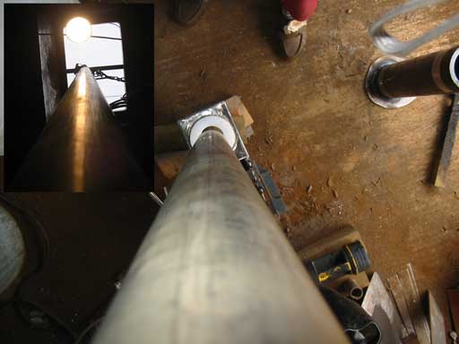
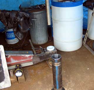
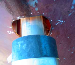
| The rudder cup was taken in to the machine shop to be machined along with the tube we just finished ( below ) and some temporary plastic bearings machined as guides. Above is an inset looking up and down the shaft at where the hull is. Gawd! What a shaft! hehe. | ||||
 Rudder tube. |
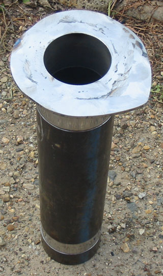
For the top
bearing there must be a "shelf" or wedge that
is flat. Even though the pipe with it's 1/2" edge
would likely be big enough, it's always nice to have a
little larger area in case things don't go as planned in
the future. The more solid reason for this plate though
is to add reinforcing strength to the tube - hull join.
Once in place there will be sides from this butting up to
the hull. The welding order should be hull first as a
pulling weld would distrort the tubes position terribly.
These measurements are crucial as we noticed that while the cup was hot from welding, it was impossible to remove the bearing as it had expanded more than the metal. Luckily ocean temperatures don't vary that much, but during a haul-out, on a hot day, the rudder would be very difficult to turn. |
|||
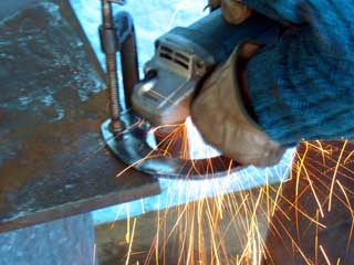
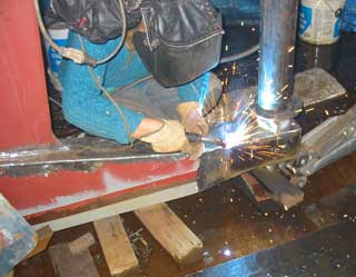
| After the speedy machine job ( thanks you guys! ) we proceeded to align the cup-box thingy we made on day 250. We were afraid of all the variables that could make this a very long and frustrating day. Will the side plates need to be cut down? Will the heel twist as we weld? How long should we allow for cooling? Is the 150 lb shaft going to be too heavy for us? We were very afraid! | ||||
| I bent a peice of the 3/8" SS rod around 2 1/2" to fit the end of the shaft for the come-along as it's very heavy, and Gena welded it on. (right) | 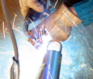 |
||
  Gena welding 'er up! |
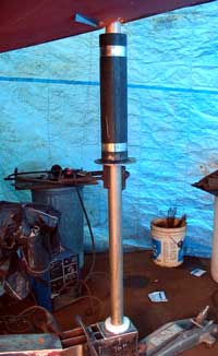
We carefully
lowered the shaft into the cup, then relesed it to see
where the present positon was. A couple of tacks needed
to be removed then the box was tapped into alignment
using a level on the shaft both forward and side. Under my direction Gena made larger tacks in various places to oppose movement during weld shrinkage. The top plate was welded end to end first and allowed to cool, then welded to the center bar to keep it from moving any further, then all around. The worst movement was the final welds along the top. Luckily they cancelled each other out and the shaft became level again. The shaft doesn't really need to be level of course, but we have plumbed the hole above so in this case yes, it does need to be. Notice in the photo to the left the water flowing across the cement. Welding is ok, but I wouldn't be plasma cutting there. 250 volts doesn't feel very nice (as I have found out) |
||
 |
|
Day 251:
8 hours - mounted rudders heel cup and level shaft.
to DAY 250 |
 Trance, Techno, Triphop |
to DAY 252 |