| Day 415 |
 |
Radar Gimbal/
hydraulic steering |
| Day 415 |
|
Radar Gimbal/
hydraulic steering |
| Before I got back to the radar gimbal, Gena insisted I get the door through the aft entry on. This prompted me to put together the latches for that door, although I didn't have to. | |
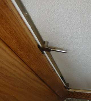 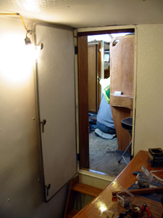 Door latches present a "hooking" hazard |
Similar to the outside hatch handles,
these would have two sides. The handle on the "open" side is the bolt so
if a pin were to break, the handle could just be unscrewed until it
falls off. A safety backup!
As can be seen, the offset cam pressed neatly against the short flatbar screwed into the door frame. Once a good alignment is accomplished, a hole will be drilled through the nut, then the bolt, and a pin inserted. I was going to use a set screw but my experience with set screws says that they will work loose and be a problem. A pin, or small bolt and nut will work fine. The only problem I can see here is the "hook hazard" of the latch sticking out ( bottom photo ) I may remedy this by putting a hand hold on the door. There needs to be one there anyway. The door will be pinned open most of the time. All went well until I got back on the radar gimbal... |
| I cut and tacked the mounting plate to the frame to check for alignment. Feet needed to be tacked on that would match the tabs on the radar arch, and were used to temporarily attach the gimbal to the deck in front of the house. | |
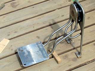 A Pretty site.... |
It swung back and forth smoothly, and was
level. That was where the "fun" ended. I sat the radar antenna on the plate and tipped it back and forth. Everything cleared well, but it seemed to bend down a long way. I pushed down on the radar and it sat there bouncing up and down for a few seconds. I tried to see where the gimbal was flexing but it seemed to be flexing everywhere. Here is something I hadn't thought about! The motion of the boat going up and down will cause this thing to bounce up and down endlessly. I checked the weight of the antenna. With the pivot arm, it was almost 60 lbs! It's a lot heavier than I remembered it to be. I should have dumped this idea when I realized a pin needed to be in plce all of the time. Duh!! |
|
| We always make plans and
research well in advance to skirt any possibilities of wasting time
"experimenting" but this one slipped by me. Totally! I should have
thrown an incredible temper tantrum at this moment but didn't. I'm not
sure why. Perhaps I knew in my subconscious all along that this wasn't
going to work.
Still, it was a terrible waste of time and
materials. All it can be is a wind doily now. What a waste! Time to go to plan B. (It's always good to think of alternative methods in case of the unlikely event of a catastrophic failure in design.) It's a little more "grass roots" and uglier, but will definitely work. |
||
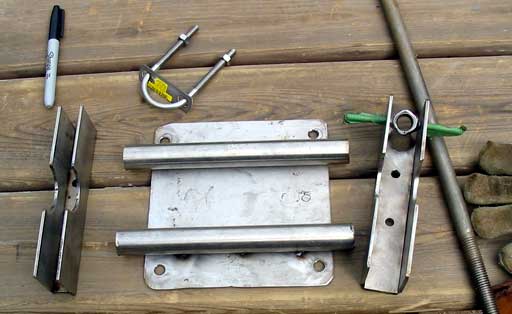
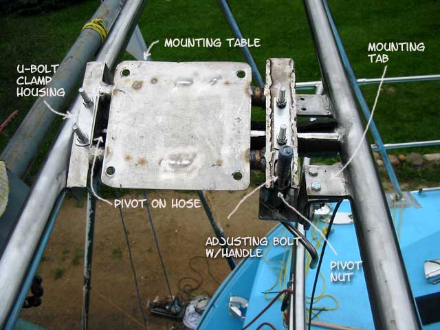
| The idea is to use the center
support bar on the arch as a pivot point for the mounting table. It's low
profile but will still allow for a tilt that will be even with the boats
max. heal. The photo to the right shows the over length cradles I made for the "U" bolts, which will be large enough to clamp around some heavy hose to act as a damper and prevent wear on the center pipe. |
 |
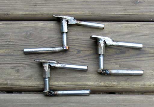
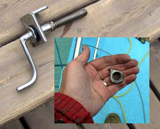
| The one end was drilled out to
mount a large nut for the adjusting crank. Welding the nut to short 1/4" SS
bolts was tricky. The second bolt had to be welded while in place requiring
carefully placed masking tape to protect from spatter during welding. The first time, one broke off as I put it through some strength tests. Seems I ground too much off. After rewelding it on, it passed with flying colors. The handle was made by bending some 1/2" rod
and welding it to some 3/4" SS threaded rod. (Something that was just laying
in the scrap pile.) Ready to go together! |
 |
 |
|
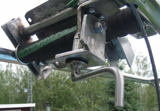
| It's a little ugly for now, but some smoothing will make it presentable. (Photo above) One of the tabs I welded on for the original gimbal was used to hold the bracket with the pivot on it for the rod/handle assembly. | |
| Care had to be taken to keep the length of the table so as to minimize forward/back movement. It could work it's way one way or the other after several adjustments, even though the heavy hose is snug. |
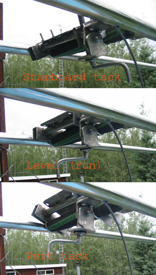 |
 It worked nicely. With a tad of grease on the threads, it is quick and easy to turn from one tack to another as shown in the photo strip (right). I must put a 1" riser on the table, probably wood, so the radar antennas case clears the bolt when on the starboard tack max position. Once the antenna is in place, I will place a large lock nut on the bolt as a stop. The one on the starboard tack seems pretty close already. |
|
| The table is strong and sturdy (I stood on it) so should work fine and stand up well. |
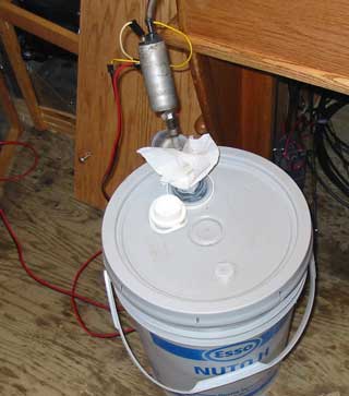
| Gena got back with the
engine work. She painted the tappet cover and baked it in the oven so it
would dry quickly. I thought this was bizarre, but it is high heat
paint.
|
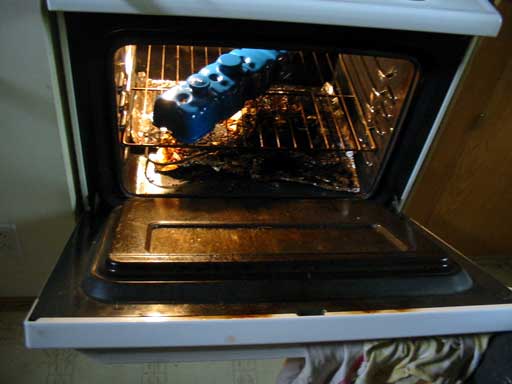 What's for dinner? |
||
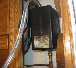
She decided
that it was time to fill the hydraulic steering system up as well. The take
up tank is higher than any pumps in the system. This allows "bleeding" off
any air bubbles caught anywhere. All lines from this unit must constantly be
angling downward to avoid bubbles.
|
|||
| I wasn't the only one
to make a big mistake recently. Gena marked the stainless hydraulic lines
for port and starboard so the steering pump in the cockpit would be going
the same way as the pump in the pilot house.
Because one of the pumps is pointing forward and the other on pointing aft, it seemed logical to switch the "P" and "S" positions, effectively crossing the pipes. One thing she forgot to consider was when the pump was turned around, clockwise become counter-clockwise. Duh! I can't laugh at her because it had me totally fooled as well! Funny how something so simple can boggle the mind. After some testing and messing with the cylinder end, the system seems to work. It felt a bit springy until all of the air bubbles were out, and the cylinder may need to be removed to completely evacuate air. Gena says that fine air bubbles in the system will eventually accumulate and the system will need to be bled again. It just takes time to get them all out. *As a tip to anyone doing a hydraulic ram system, make sure the nipples are at the top of the cylinder! This is where you will be bleeding it. |
|||
Day 415:
14 hours: Made "new" radar antenna gimbal, mounted aft door and made latches,
filled hydraulics.
 Get Fresh! |