|
|
|
|
|
|
|
|
|
|
|
|
ACCORD WHAT'S NEXT
(Prototype)
This module is in the prototyping and development phase as of fall 2025. As new features are added they will be added here!
 |
|
||||||||||||||||||||||
What is it??
The What's Next is a universal CV/Gate/Trigger I/O module that obeys Algorithms
that you enter into memory to offer ultimate control around you rack. No matter
how big or small a function is assigned the response is predictable and
accurate.
For example, if your algorithm is set to simply add the CV input at Jack A with the input at Jack B, with the result at jack C, the inputs and outputs are automatically configured and a 1.00 volt input on A and B with result in 2.00 volts at jack C. Or, perhaps you only want this voltage to update when Jack D has a high on it. A conditional statement in front of the A+B statement will only allow updates to Jack C when Jack D is set to high.
You can probably think of all of the benefits of this right away considering doing this with standard modules would be cumbersome and use up VCA or logic modules that could be used for a different function. To make things even more interesting, there's also Sequencers, LFO's, Delays, and Envelope generators built in that can be triggered whenever you want, play at any speed, and provide an accurate reproduction of previous sessions every time thanks to flash memory.
One of the first questions I was asked when considering this module a few months ago was "what if you select a different User Program (preset) and outputs become patched to outputs of other modules?". My response was that after a Program (scene?) change, the outputs are all held in a high impedance state while a test for loading on the jacks determines if any are going to collide. This is done with very fast low voltage pulses that couldn't possibly damage another module's output. The LED will flash, in what ever color, and won't be an output until the jack is cleared.
Below I am adding features as they are included. Below that is the development dates and progress. Please not that this may not be updated until late December as I will be overseas and may not be able to access the website from there due to the political climate.
Formula Blocks:
At the moment there are 9 blocks, each of which can contain an algorithm (set of
statements) and can hold up to 32 lines. These blocks are always active once the
"Run" button is pressed. So any changes on any inputs will follow your rules.
There are a number of simple presets to choose from to quickly load a block for
a specific function. If you name a block according to it's function, then it
will be identifyable to load into a different block or user program.
Run and Stop buttons
To freeze the states, hit the "Stop" button. This will not release the outputs
unless the stop button is held. Outputs are also released when a "user program"
is first loaded.
Gate and triggers use logic operators:
If a Gate (i.e. GT.A) is set in a statement then the choices following it with
be logic like or V, and Λ, xor(+), drop
↓, or rise ↑ so you don't need to go
through a lot of operators in the drop down. A gate GT.x or trigger (exclusively
drop ↓, or rise
↑ ) mentioned makes the associated jack an input, but
doesn't limit it to being logic. This means a CV.x can still be used anywhere if
it's a combination signal that is desired.
The output that is (eventually) where the result will go, unless it is just to
start an internal envelope etc, can also have both CV and gate/trigger at the
same time, so one won't block out the other. A use case would be a gate that
brings an output to only +3 volts because a CV assigned to the same jack is
sitting at -2V effectively allowing through-zero modules to function while
others don't on the same output.
Data type profiling:
If a VARn (in-block local variable) or BUSn is used as a line's destination,
i.e. BUS2=CV.F÷CV.B, then the variable will
become that data type. The declared variable won't be able to be used with
opposite types, i.e. OUTD=GT.AΛBUS2
with only GT.x and TG.x showing (or HI or LO for directly setting OUTD in
this case). Initially, an undeclared variable brought to an output will color as
CV type (red)
As a positive ( or maybe not) Outputs can be re-declared from one type to another as a result of a conditional of situation. In other words, limits have not been placed. Inputs can be used in multiple ways all at once, i.e. Jack A could be included as a downward trigger in a conditional (so will flash blue) but be included in a calculation or Gate scenario for switching through another output, etc. all at once. This may or may not yield the results you are looking for, but can be done none-the-less.
Conditional Statements:
As expected conditional statements can be placed before any other statements so
that only when the condition is met the rest of the block will execute. For.
example.
IF CV.A>1.000V --> statement(s ) following --> ELSE CV.A>CV.B
--> statement(s) following. This example tests for both CV.A being greater than
one volt and also CV.A being higher the CV.B. If the former is true, the first
statement(s) will execute, whereas if only the latter is true, the second
statement(s) will execute.
If two (or more) conditions must be true to cause events to execute: IF CV.A>1.000V
followed by AND CV.A<2.000V can be written before events.
Embedded events placed between like statements can be used,
but can become complex.
i.e. IF CV.A>0.000V OUTB=1.000V AND CV.A<2.000V OUTC=1.000V.
If CV.A is 3 volts, OUTB=1 volt, but OUTC is unchanged.
"AND", "OR", "XOR", or "NOT" can be inserted between conditionals to logically handle the the two. There can be more than one AND/OR/XOR/NOT, but due to the inconvenience of situating brackets "( )" any logical will be interpreted as in series. i.e. c1 AND c2 OR c3 will be seen as (c1 AND c2) or c3, not as c1 AND (c2 OR c3). This can be fixed by simply ordering the last part first: c2 OR c3 AND c1.
Complex Algorithms:
For really lengthy or complicated Blocks, VAR's can be used to swap data
around without affecting any outputs. i.e. VAR1=CV.A x LFO2 OUTC=VAR1÷4
For global variables to use the data in other blocks, BUS's can be used.
Numeric Interpretations:
For a numeric declaration, 3 types can be used: 0.000v (-5.000 to +5.000 or
-9.999 to + 9.999), a voltage accurate value; 000 (-999 to 999), a whole number
declaration interpreted as volts or percentage in special cases, and N000 (N000
to N127) as a (Midi, CV) Note declaration. (For example N036 seen as C3 note, or
CV voltage 1.000 volts - if global CV offset is -2.000 volts).
Certain numbers are considered as more decimal places, i.e. 0.083 (one semitone)
will be seen mathematically as 0.08333 to maintain accuracy. Powers are to
several decimal places.
Delays:
Delay statements, i.e. DELAY=1000MS, doesn't prevent other Blocks from
executing, rather just delays the execution of "this" block and the
statements following. This could be useful if you wanted a clock-stop to roll a
filter a certain way, or levels to drop off etc. using a multed input from the
system clock to a Jack. An example might be CV.B=ENV1OUT
IF TG.A = ↑
DELAY=800MS ENV1=RUN. A constant clock keeps resetting
delay until there is no clock then the internal ENV1 is triggered. Another use
might be just to sequence a series of events, although one of the Sequencers
could if the event's are evenly spaced. If not, then delays! I.e. CV.A=CV.C
IF GT.B=HI DELAY=200MS CV.A=CV.C+1.000V
DELAY=300MS CV.A=CV.C This would add an
octave shifting warble to a VCO on CV.A whenever GT.B is high.
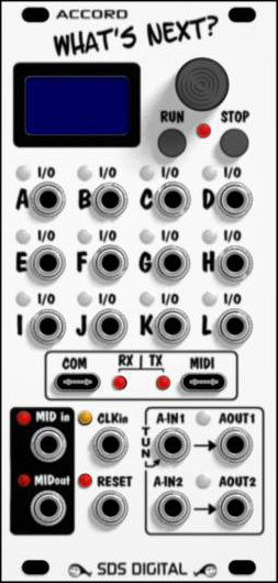
| July 22 2025 | Panel design decided upon. 12 HP with 20 jacks and a color display. The 12 I/O jacks have RGB LED's to indicate status, signal direction, and type of signal. Colors have yet to be decided upon. |
| July 26 2025 | Successful math algorithms developed in computer to demonstrate entire concept including method of entity selection (vars, I/O, operands etc) |
| July 31 2025 | Concept schematics developed for basic functioning, parts count etc |
| Aug 07 2025 | Finer schematics with proper values drawn up to begin PCB's |
| Aug 09 2025 | Prototype PCB's designed and etched / populated over a few days. The final design of course will be somewhat different as a few parts had to be substituted for what could be available at the time. The final design will perform much faster and more smoothly than this design (happily!) |
| Sept 19 2025 | LCD drivers created (scratch not from libraries) and simple tests. Initial fonts have been developed with non-monospaced characters so they can be large yet fit the width! The decision to zoom on editing a math expression with auto-pan etc. hasn't been made, but the huge font makes it very easy to read. The Normal font (Tahoma) is wide and bold so also easy to read. |
| Oct 10 2025 | Frequency 2 CV implementation. Works! |
| Oct 20 2025 | Decided on Menu layout, Quick Boxes. Changed Block Layout. QB Button GFX attempt 1. |
| Nov 7 2025 | Implemented 5th (& final hopefully!) Block Scan method |
| Nov 12 2025 | Implemented new conditionals method. Works 100% |
| Nov 20 2025 | Fixed colors (more or less) and standardized. |
| Nov 23 2025 | Added "Menu Zoom" for all entries & adjustments. Blocks included. |
| Dec 1 2025 | Changed Flash memory organization, forward compatible. |
| Dec 4 2025 | Envelope graphing started. May revise. |
| Dec 18 2025 | Last updates before break. |
Contact: freshnel@freshnelly.com
| This is the introduction to the Accord What's Next that shows the basic theory and the prototype operational in early test state. |

Web Design by Yours Truly! I know it
looks like something out of the 90's when a 1 Mb webpage was unacceptably large.
We strive to separate ourselves from energy consuming bandwidth-heavy script and
other wasteful environmental unfriendliness
toward this beautiful blue pearl in space we all call home. I urge you to do the
same please. It feels good!
Last Update Sept 21 2025