"Show-In-A-Box"
SDS MySynth II Stereo Mono-Synth!
 
   
  Of all the coolest projects I've ever designed, this one is right up there! This tiny synth may be unique in all the world I don't know, but if you're into making / DIY'ing your own synths, this page will be of interest to you!   It is fully MIDI programmable (128 "instrument" slots) and controllable (using a PC or any knob style MIDI) and in stereo!

First I'll tell "the story" on why it's called the mySynth 2 (a couple of excerpts from the user manual).

  This is the second synth I have designed, my first being the cereal-box encased Morse-code oscillator I found at a scrap yard when I was 13,
modified with many switches, caps, and resistors. Kraftwerk was yet to hit North America so the sounds it made were alien, almost scary to all that
heard it back then!    The SDS mySynth II, named in sequence from that ancient box of “doom”, has a few more features but no knobs and switches… well physically anyway.

  I decided the the SIAB box needs some form of oscillator or "not GM MIDI" sound, for those tiny setups that would ordinarily require the Korg Synth plugged in.
After grappling with several designs, and even searching on the 'net (only found analog-knobby style synths others are building) I came up with the idea for this synth.

  The SDS mySynth II is digitally controlled, but is very analog in nature. Digital synths, VST synths, and MIDI keyboards all use digital signal processing to create the sound. This works well in numbers, but the really high-end pianos use actual wave samples from real pianos. The SDS mySynth II also uses wave samples as the the main Oscillator, instead of the old CV Oscillator, or a digitally generated wave shape. There is no digital processing and the wave’s original nuances will track with notes and octaves. Not only the pitch changes with frequency, but the nuances change as well. This creates a very unique synth sound, crisp on highs and serendipitous on lows.

  All of the control of the audio from then on is done as analogue. The wave sample has already been processed ( unless it’s a natural sound sample like voice or an instrument ) So you have the “big synth” sound without the circuitry complexity and size.

  As with most synth makers, I crave that analog sound, and that is for the most part what the mySynth2 is. Using the standard waveform generator technique was my first choice, but I wanted something a bit more versatile that sine/square/ramp etc. Also it *must* be COMPLETELY MIDI controllable.
Anyway, here's what I came up with!

 A "wave-table" synth is what someone has named this method. You take a wave shape, then filter and manipulate it until it sounds great. My "wave-table" 
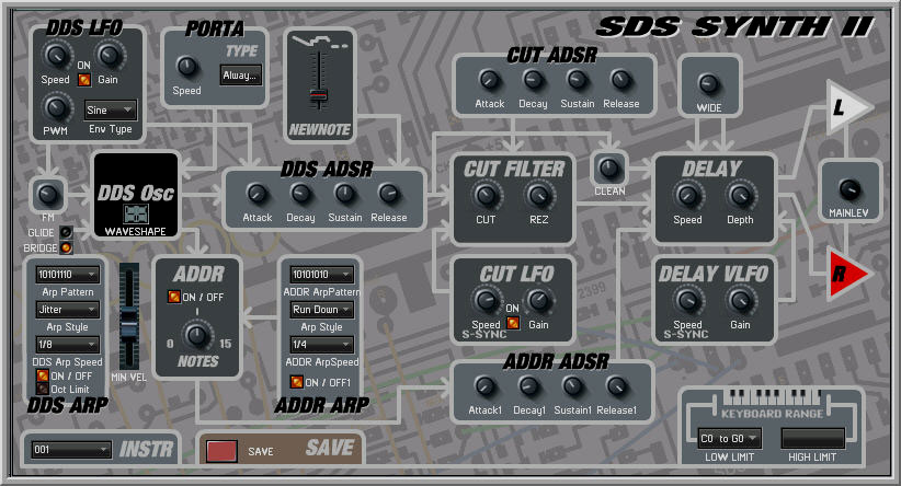
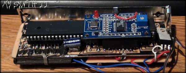
is in the form of an old style UV EPROM (128k), although any parallel PROM/FlashROM could be used, as long as the addressing scheme is simple.

  Looking at the diagram to the right, the EPROM is inside the DDS Osc. box. The DDS (Direct Digital Synthesis) chip, the AD-9850, is on a module that can be seen as the blue board in the top photos. I have played with these since they were a $50 chip over a decade ago, but now can be bought from China for $5 already mounted with a 120 MHz osc. chip!

  This DDS clocks a 4040 12 bit counter (I only use 8 bits) to get a 256 point waveform. Even though I used a PIC16F887 for this synth, I used an Arduino (ATMEGA) to connect up the EPROM on the wish-board...It was then that I realized I no longer have an EPROM Programmer!! Duh! I chucked the last one I built that ran off of a COCO III computer's expansion bay, along with the COCO III when we moved on to the boat.

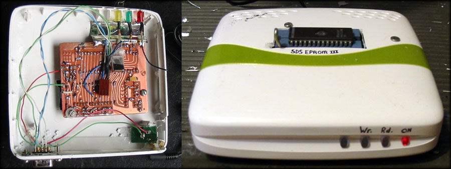
  So my first order of affairs was to make one of those. Somehow it seemed a lot simpler to do than the last time, back in the 90's. I actually made one before that with dip switches and a "program" button to program each byte one at a time. One mistake and it's back to the UV eraser to start all over again!

The whole thing was done by the next day.
I found an old router box someone gave me which would fit the bill to protect the "innards" from dust. I really pride in re-using thrown away stuff, even before the re-use / recycle idea became the norm. I think it's because as kids, we always had to make do with whatever was around ( that was free! ) to keep busy.

Anyway!

  Some LEDS show the status of the programmer. It links to the computer via standard RS-232 @9600BPS (8mhz xtal)

The schematic, program for the PIC16F887, and schematic is in this: EEPROM-pgmr.zip
The user manual has the instructions to use.

Then I wrote a special flash program to scan

waves from a stereo wave file (using hex-edit XVI32), then select and copy and paste the ASCII-HEX code into the big window.
  Then press "decode" to get the wave into binary and then "Graphic" to view the wave. Give it a try with this .wav section if you'd like!

B7 F2 8C F8 B2 F2 C9 F5 52 F3 75 F2 53 F6 66 F1 9A F8 6B F1 55 F9 24 F2 0C FA C8 F2 97 FB 77 F3 CE FC 2C F6 C9 FB 40 F9 8F FB B6 F9 37 FD A0 FA 96 FD F3 FB EA FB 7A FD F3 FA B9 FC 40 FB 20 FD 2A FC 36 FF 71 FB E4 00 81 FC 77 FE 17 01 41 FD AD 05 23 FD A7 06 22 FE F8 06 8B FD 6D 07 49 FE 4D 08 3A 02 A2 07 E9 07 F4 06 5B 08 58 06 7C 08 CF 04 A8 08 F3 02 4D 09 7C 02 10 08 F6 02 CF 07 2C 04 08 08 EE 04 7D 07 3D 05 37 04 E6 06 D3 02 D4 09 C9 02 DB 0A 56 03 2B 0B 15 04 5E 0B 53 04 59 0C 85 05 37 0B D6 08 68 09 4B 09 AD 08 2B 09 F7 08 25 09 A0 06 05 0A 9F 03 97 08 4F 01 F6 06 74 00 B9 06 A0 FE 45 08 C2 FC 45 05 7B FD A8 01 1E 01 31 FF 47 02 67 FE 46 01 9D FC C7 FF B2 FA 0C FF 77 FB 97 FD 2D 00 76 FB 22 01 6D F9 86 FF 6F F7 2C FE 7C F4 A6 FD 39 F2 CA FB 6A F1 C6 F9 9F F1 EF F8 5B F2 83 F8 A4 F2 2F F5 41 F3 43 F2 C7 F5 76 F1 21 F8 9C F1 36 F9 68 F2 EA F9 FB F2 55 FB DD F3 6D FC 12 F7 09 FC 8F F9 B0 FB FF F9 FF FC EB FA 97 FD 80 FC 61 FC 8C FD 37 FB D1 FC 58 FB 76 FD 04 FC 0A 00 D9 FB C8 00 8B FC 53 FE 80 00 44 FD 08 05 7A FD D4 06 3C FE 10 07 98 FD 8D 07 C7 FE 2F 08 82 03 F1 07 66 08 2B 07 61 08 9C 06 80 08 4F 05 D8 08 73 03 29 09 9D 02 D6 07 F5 02 C6 07 F9 03 29 08 E0 04 FE 06 44 05 C8 03 A5 06 AF 02 43 09 BE 02 D9 0A 59 03 0B 0B F9 03 59 0B 3F 04 F5 0B E7 05 81 0B 06 09 8F 09 02 09 B6 08 F3 08 BA 08 06 09 31 07 C7 09 ED 03 EB 07 92 01 9C 06 4B 00 CC 06 F9 FE 08 08 E1 FC 56 04 1F FD 03 01 2A 00 C7 FE 60 02 20 FE 4D 01 FF FB F2 FF 85 FA DD FE FD FB CF FD D2 00 96 FB B9 00 A5 F9 40 FF AE F7 F2 FD 11 F5 84 FD 59 F2 46 FB 5B F1 9B F9 68 F1 EE F8 16 F2 5C F8 97 F2 A4 F4 08 F3 27 F2 12 F5 91 F1 F7 F7 D6 F1 08 F9 AC F2 D2 F9 38 F3 E9 FA 5E F4 6F FC F7 F7 2A FC CD F9 B9 FB 4F FA A3 FC 3A FB 0C FE 08 FD B9 FC 88 FD 74 FB FB FC 39 FB E0 FD 21 FC D1 00 18 FC 8C 00 51 FC 3C FE 8C FF 4D FD ED 04 D5 FD F8 06 3E FE 3A 07 BB FD 7C 07 5E FF 51 08 DB 04 31 08 A4 08 62 07 6A 08 D3 06 7E 08 02 06 07 09 C4 03 E2 08 AB 02 A9 07 E2 02 BD 07 C2 03 40 08 EC 04 69 06 2E 05 66 03 14 06 8C 02 F9 08 B1 02 DC 0A 56 03 F7 0A D8 03 22 0B 32 04 D2 0B 58 06 E1 0B 09 09 9E 09 BA 08 72 08 B4 08 F5 08 F9 08 D0 07 68 09 35 04 4B 07 A2 01 4B 06 42 00 FD 06 6C FF 93 07 B4 FC 71 03 4A FC 62 00 97 FF 74 FE B3 02 C4 FD 5B 01 6E FB 00 00 6F FA CC FE B2 FC 25 FE 3A 01 AA FB 55 00 D0 F9 FB FE 2C F8 D1 FD 86 F5 4A FD 6B F2 CC FA 48 F1 7E F9 2C F1 02 F9 F0 F1 1A F8 72 F2 2C F4 A8 F2 1A F2 89 F4 B6 F1 D2 F7 18 F2 D2 F8 EE F2 AE F9 7D F3 92 FA FD F4 83 FC C6 F8 28 FC 02 FA B5 FB A3 FA 81 FC 99 FB 5B FE 82 FD 01 FD 76 FD B7 FB 37 FD 38 FB 6B FE 4B FC 7B 01 24 FC 3B 00 32 FC 2C FE F7 FE 61 FD 99 04 2C FE D4 06 2F FE 5E 07 F1 FD 7F 07 1A 00 6F 08 15 06 47 08 B6 08 A3 07 76 08 17 07 7B 08 68 06 2F 09 35 04 8B 08 E8 02 8D 07 E2 02 BB 07 A4 03 3F 08 BF 04 BD 05 1F 05 0F 03 DD 05 6C 02 99 08 A2 02 7C 0A 4F 03 ED 0A B3 03 F8 0A 2F 04 B4 0B D2 06 A8 0B E6 08 E9 09 7A 08 84 08 72 08 E8 08 F4 08 D5 07 E5 08 C8 04 C2 06 EF 01 04 06 73 00 3E 07 4C FF DF 06 20 FD A3 02 52 FC C4 FF 11 FF 34 FE CF 01 50 FD 85 01 F2 FA 0E 00 6F FA F5 FE 8F FD F4 FD 67 01 FE FB FC FF FD F9 B4 FE 67 F8 C3 FD

  Up to 64 waves can be programmed, then backed up on the computer. It's a bit buggie, but does the job. Watching the program speed of "program All" I realized how spoiled we have become with all our new tech, it took FOR-EVER!!


 Back to the mySynth2-DDS vs. Analog Oscillators
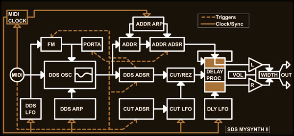
The basic block diagram, for me anyway, seems complicated to look at, but I'll try to explain the sections and how they interact.

  All Synths have a chain that starts with one or more oscillators, followed by an envelope (ADSR or AHDSR), then a filter to allow certain frequencies to pass, not necessarily in that order. Some synths have a good many controls; too many!  Even the small mySynth II has 40 knob controls (57 MIDI CC's total including drum modifiers). But these are needed for basic sound shaping.

I.M.H.O.    DDS Wave Oscillator vs. CV Oscillator:
  All of the CV (control voltage) Oscillator fans will shun the DDS Wave Oscillator saying it’s too digital in nature. Yes, the wave form has a digital resolution (48 kHz original), but the fact that the note can be higher and clearer with varying note/sample rate along with it’s nuances kind of nulls the point!  The DDS Oscillator has one major advantage over the CV Oscillator: Precision. It remains chromatically precise to within fractions of a Hz.!  I.E. Nobody could say it’s “off frequency”!
  Of course, the simplicity of an analog oscillator means many can be constructed into a design without the cost/microcontroller overhead of controlling multiple wave tables at the same time. So I guess it's just what the design is to do. I don't much like tweaking knobs (other than in the studio) and in a live situation it can be a disaster if your day is a bit "off". Because of this, MIDI must control all of the parameters, and in order to do that, stuff needs to be stable and predictable. Like a DDS Oscillator.

  Another real advantage of the DDS (Direct Digital Synthesis) Oscillator is that it’s fast! It can change frequencies faster than the frequency itself. In an Arpeggiation, the response time is unequalled.  There’s no over-shoot or Portamento (unless Portamento is turned on!) and no drift with temperature at all.  Driving a wave sample rate with a high frequency CV oscillator (non-PLL) is fairly inaccurate by comparison (I’ve tried) as non-linearity becomes chronic (excuse the pun!)


If the mySynth2 had a "box", this is what it'd look like! Actually, this is the FL Studio Dashboard I made for it. It looks all VST-ish... but hey! No latency!

This control panel also shows the flow, maybe a little better. Here's the key sections:

ADSR's:

The mySynth has 3 ADSR's (Attack, Decay, Sustain, Release) in total:
-The DDS ADSR shapes signal from the DDS wave table, and feeds it into the Cut/Rez filter, and also into the "clean" bypass.
-The Cut ADSR shapes the Cut filter frequency with each note if turned on. (A, S, or D > 0)
-The ADDR ADSR shapes the unique Addr mix, derived from 4 address points from the EPROM address!
This is a really cool feature the adds "sparkle" to the notes, and is mostly on it's own stereo channel so adds depth.

The ADDR:

 One feature I really like is the ADDR mix. Besides being a simple mix of 4 address points (octaves) from the EPROM Address, different combinations of the 4 can be selected using the "ADDR Notes" control (if turned on).

This allows for 15 combinations (1+2+4+8) binarily. As if this isn't enough, various combinations of these notes can be Arpeggiated! There are 16 Arp styles, that sequence "notes" in different orders (such as roll up, roll down, warble etc) I have programmed, then there are the patterns these notes will be stepped with. So a light twinkle to a complex electronic sound can be super-imposed onto the original wave table's wave.

Because the ADDR is coming from divided DDS signal, it follows any bends, FM, and Portamento's. This signal is fed into the delay section, which expands it out to a very 3 dimensional sound. When a simple non-arp'ed signal is sent, the higher octaves can add some wonderful peaks to a bass line.

The DDS LFO:

 The DDS LFO can control the level of a DDS ADSR sustain/release zone with various envelopes (sine, ramps, square, pwm, ADDR note-shift, Cut LFO Mix etc) but can also control the DDS frequency using the FM knob as intensity of the Frequency Modulation. The LFO speed is a semi-locked tempo multiplier/divider. This means if set between "markers" can run out of sync with the tempo. Why not just make a switch "tempo on/off"? Because this method allows momentary synchronization, then release, then re-sync. Very interesting and chaotic!

Portamento:

 My portamento design has a speed control as usual, but can do constant time (always takes same time no matter how far notes are apart) and constant rate (close notes are almost not noticeably porta'ing but further notes can take much longer to reach). Sub settings include up only, down only, both, on hold up only, etc.
I didn't include a glissando as notes can do that just fine in my app. I wasn't originally planning to add a portamento, but really glad I did! Works with the Arp's too!

The Arpeggiator:

 A good 30% of the month it took to design and build this synth was probably used working on the Arpeggiators. Getting them to sync properly an agreeably was the greatest challenge, and next time I build a synth, it'll be an Arduino or bigger! This is a lot of overhead for the poor little PIC16F887 to handle, (It has 8k prog-mem) and I almost failed.
 The speed is locked to tempo ranged from 1/32 down to 2.5 bars in logical steps. There is an octave lock, which keeps notes from jumping tot he next octave, and a "minimum velocity" control which is really handy when performing by hand. The Arp also has a glide option, which won't re-start the ADSR on each note, just follow it into release oblivion. Then there's a bridge control to allow glide without the oblivion!
 The Arp and the way it interacts with the other Arp is a bit beyond what I want to to post here, so if you're hooked, check out the
 user manual (opens with wordpad/office etc)

Cut LFO:

 This produces those legendary pans of Cut/Rez we all love! It is semi-synced like the DDS LFO, but only does a sine wave. It can be super-imposed with the Cut ADSR at sustain, with varied results depending if the gain is on the + side or the - side.

Delay VLFO:

 I have added the V to LFO to describe a Very Low Frequency Oscillator. With the delay being used as a chorus (tight) slower shifts are barely noticeable, but if the delay is an echo, it can "move" the notes up and down, hence a VLFO is needed.

Miscellaneous Controls:

New Note:
 The "New Note" control was a late addition. When there is a non-glide/bridged arp in progress, it can be annoying if the attack it set in the slower region. It almost sounds like music is playing backwards, which is ok if you're recording it back wards! LoL! This slider pulls up the attack start so the note has 2 attacks. This can create some cool effects too!
Wide:
 The "Wide" control is sort of like a stereo wide control, but shifts the center as well. It's pretty hard to describe the effect without hearing it. Sorry!
Keyboard Range:
 The keyboard range low/high sets the area the mySynth will respond inside of. Other notes are ignored. This is great for a split keyboard arrangement playing live. If the lower range is higher than the upper, the whole keyboard is used, but the notes control where the Cut/Rez filter and Clean is. I call it "Cut/Clean Tracking" and it's useful for smoothing/highlighting.
Save & Instrument:
 Once all of the controls are set nicely, and the sound is perfect, SAVE saves it to one of the "instruments" (1-128). This is permanent until changed (of course!)

Conclusions:

 After a really amazing project that I didn't know would even sound good when I started, all I can say is "If you're trying to decide on whether or not to DIY a synth, DO IT!"
This has been the most amazing month for me. Hearing my baby come to life, then tweaking and customizing it until I ran out of memory, was a real love affair!

And wow, the quality of sound over VST's or even a wave file is incredible. Now I know what drives  all of those analog / CV synth lovers out there. It's very cool!

Have a listen:
 In the future (once the rest of the SIAB is done) I will be creating music with the mySynth, but for now I only have some demo/test stuff to show off:


mySynth2-1.mp3
Chunk 1: Trance Cut/Rez
Chunk2: Porta chaos to alien depth
Chunk 3: Theremin simulation (LFO)
100% MySynth2 !
mySynth2-2.mp3
Trying Out Program Change "On-the-fly" and live Arping. Alone except for some drums. This clip hi-lites the ADDR arp "sparkles"(last bit)
mySynth2-3.mp3
My First Jam with MySynth2.. shortened because it was a long recording.  Just playing it live with my MIDI keyboard, strings, SDS Tap Drums, and changing between presets!


-Design-

The electronics may interest you some, well maybe not, but here it is anyway!

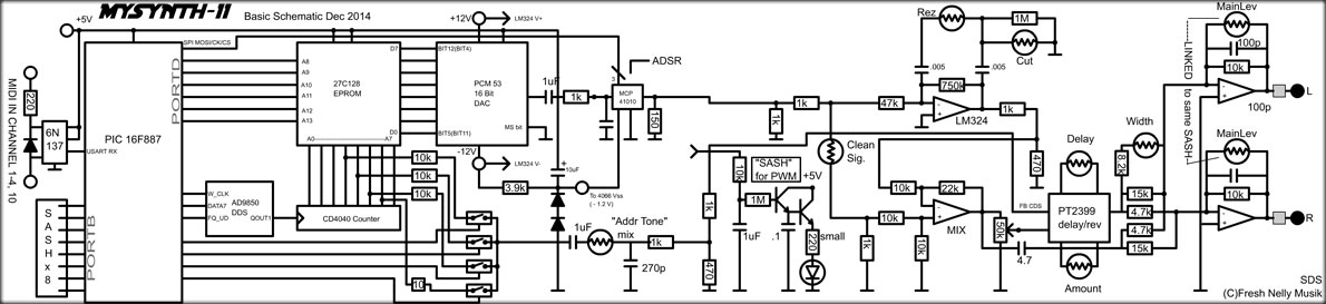
 I don't know if a DDS has ever been used this way, but most likely.  The AD9850 is controlled via a simple SPI-like serial (or parallel if speed's your thing) interface. My first DDS was so new, the evaluation board was hundreds of dollars, so I just followed the LPF specs etc. and built one. Now you van buy the whole thing ready to go for less than $5!

The basic schematic below is a pretty good guide, and pretty close except the PT2399 circuit, which is a "pick and choose" thing. I used the schematic that's in the datasheet, with a couple of tweaks.

The one thing that is different is the PCM53 is really an 8-bit DAC  because I discovered the difference between a wave 8 bits and 16 bits in this application is not noticeable at all! Go figure. I still used the PCM53, as I couldn't find my 8 bit DAC anywhere!

The MCP4010 is one of those serial (SPI) volume control chips. They work pretty smoothly, I was surprised. All of the other levels are controlled by SASH (Sample-and-sorta-hold) circuits similar to the ones being used in the rest of the SIAB project in that CDS photocells are used with LEDs, but with PWM not a 12 bit DAC,

 The LED/CDS couples are mated through the space between the pc board sandwich. (The circles are the CDS cells) 3 layers of 3-M foam tape stops the light from crossing/entering.

I've adapted the SASH design recently in the "Distortion PIC" board, using a DAC and curve to take away the curve of the LED-CDS transition. It seems more linear for sure!

 I have been using Macromedia Flash to create the curves and make a table (using strings etc) that I can just copy and paste into the PIC MPASM program. I've also done it with Arduino, sine waves, and other curves. Makes it easy. How innovative is that!?
 The .swf is below. You can see the kind of curve we're dealing with.
It's 0-127 in, and 0-255 out.


PT2399 delay chips:

 If you're not familiar with these cool chips (they're not new!) and you like making audio stuff, you're really missing out on something. They can make a boring old oscillator sound like a Poly-Moog... well not quite, but even one can add another dimension to sound.

 I'm not familiar with any product these have been used in, perhaps those "Wide" buttons on old ghetto-blasters? They are in high demand with both DIY guitar peddlers, and the more "pro" pedals out there. They are similar to the old BBD (Bucket Brigade) devices found in CB echo mikes, but way higher resolution and sample rates. They also, according to the data sheet, use an ADC---> 4096 bytes --->DAC setup complete with nulling circuitry.

Op Amps:

 The op-Amps are part of a 4 element LM324, but I'm getting a little peeved with those chips in audio applications. It seems some (not all) of them have distortion on the zero-crossing point (dual +/- 12V supply) that requires DC to be shoved in so it's away from that area. I didn't have any problems with this synth, but had endless problems with the DistortionPIC module, until I figured out what it was.

PCM53 16 bit DAC

 I bought a couple of these off of eBay (China) and I know they're old because the datasheet looks like it was rubbed off a stone wall in some cave! Also because the "Q0" is actually the MSB of the 16 bit byte. It seems like it's well balanced though, and can produce the full range (+/- 12V in this case) linearly.

 I bought these chips for the Sampler Project, but only need one right? That project *does* need to be 16 bits (because it's my voice getting sampled dammit!)

The PIC Program:
 The 16F887, and many PIC chips now have the ability to "self program". A lot of programmers were unsure if this was a good idea because "the chip could be ever self-reprogramming then become intelligent, self aware, and take over the planet! We'd have no recourse because the program would be unrecognizable!" That's a rough quote of someone in the forums haha!
This chip already has a 1K EEPROM built in, but with a slightly different method of programming, the whole program memory can become an EEPROM. In the mySynth II there's enough memory to save 128 sets of the 50 controls (it's a 12 bit machine so I used the excess nibbles too!) and 8 drum kits, thusly becoming presets.

 The MIDI routines (from the USART) have been set up to deal with running status (an evil MIDI trick) and inserted MIDI clocks. These two things are what most frustrates MIDI hardware programmers and makes certain keyboards not work with certain sequencers etc. It is mentioned in the MIDI Spec. but for some reason people miss it. I experienced the frustration about 8 years ago and through testing and the software MIDI-Ox, I figured out what was happening. Akai "Professional" didn't (see the MPX-8 page!) much to the chagrin of many of their customers. I'm kinda proud of that. I told them the problem, and everyone was begging for a firmware update, and . .  nothing!

 The mySynth II was a challenge, and if I'd have had more space I would've added more features yet, but really, it's chock full! Down to < 140 words (instructions) left, hmm, I suppose I could've added a tiny bit more.


Stuff I've Learned:

1-I hadn't considered what I was doing when I designed the "Wavetable" part of the synth. Heck I didn't even realize that a wave table was this. It has surpassed my expectations on
   8 bit audio quality. I suppose it's because the reproduction is repetitive, so it sounds intentional or just becomes the sound itself.
2-The
calculation of notes (beyond octave which is easy, x2) is Frequency x 2^(note#/12) , which seems pretty obvious now! Thanks again Wiki! I can see why mathmeticians are so
   interested in music. I has piqued my curiosity for math again (of which I'm not a big fan generally)
3-Mono-Synths are good after all! Before we lived on a sailboat, I had a CS-10. I hated it (so much tweaking) but eventually used it in some now obscure songs
  ("2"-Girlz2Men-Fresh Nelly Musik 2004) With a MIDI interface, and some address taps, and a delay, a mono-synth becomes a beautiful thing! I want it back.
4-Old EPROM's are still useful for some things! Parallel interfacing is a bit old school if you're outside of a PC, but it's way faster! The Sampler will also be parallel.
5-Getting a great sound from a synth is easier than I thought. Just a basic knowledge of sysnth structure is enough, I learned all I know about that from messing with an old
   100 lb Moog, a Kawai SX-210, a CS-10 and VST synths in FL Studio.
6-Self programming microcontrollers such as the PIC16F887 can be a powerful one chip solution. 128 board presets plus drum presets, all using partial program space. Cool!

Well, that's pretty much it for the mySynth. I'm not posting the .HEX for the PIC as most of you are using Arduinos and *I* would use one next time! PIC sucks if build time is an issue, they take forever to program all in assembly. I haven't even filled the EPROM with waveforms yet, and only 30 or so instruments have been saved thus far. The PIC16F887 can program itself requiring no external EEPROM for PC's which is nice. I hope I've inspired someone!
Cheers!  Sandrine*


   This was the SDS mySynth II page!

   to  The Recorder
or... Back to Show-In-A-Box

 Feb. 23rd  2015


Disclaimer: This is not an instructional page to build or manufacture the above project, nor are there any guarantees of accuracy herein.
This page is an "of interest" discussion, and the project is intended for my own personal use.
If you have any questions, or wish to pursue this project, you may contact me (Sandra) at fresh(at)freshnelly.com