Live sampling,
especially with hardware and MIDI automation in a song, has been a desire of
mine for some time now, and it's going to become reality.
With all of the technology we have and incredible music hardware, it seems
the impossible dream to have an automated Sample recorder/player that works
with a non-proprietary system like standard MIDI! Maybe there is something
out there, but in a portable format? With no latency?
This sampler will
slice, dice, granulize, delay, loop, and sync to a standard MIDI clock
seamlessly. I don't want to go with Arduino because it won't be fast enough
to real-time sample, store, and retrieve 16 bit wide data at decent audio
sample rates. This is a job for PIC, until I can better understand/untangle
the ATMEL systems and ATMEL Studio 6. Maybe next year's project!
Any of you
who have thought about such a lofty goal have probably run into the RAM vs.
access time issue. It's can't be done serially, flashing data is too
slow (and limited and cumbersome) and SRAM/Pseudo SRAM's are just too small
for a decent recording time. The ISD 15104 has a decent recording time, but
the addressing resolution is 4096 bytes, which equates to 1/8 second at
standard sample rates. This is great for a telephone answering machine, or
pocket voice recorder, or even a D.A.T., but not for synchronized record
playback.
That 1/8
second is a nightmare for alignment and makes seamless looping impossible
because the termination of a recording only happens at that address point,
which if late, will have a "hole" in the audio or a skipped portion that is
very noticeable (unfortunately). I have covered attempted correction on the
showbox-recorder.htm
page. I am still going to use it, but as just a sample recorder for
pre-recorded FX (waves lapping, wind, birds, footsteps, etc) that are
required in a song, but where timing isn't super important.
SDRAM:
The real solution is to somehow manage an SDRAM (Sync. Dynamic Random
Access Memory) which is a smaller version of what is still used in PC's
today. After some serious research in the (somewhat huge!) datasheet, I
think it can be done at 20MHz clock rates with a PIC chip. I have wrote a
basic program for Record/Play and the simulation is within the SDRAM refresh
timing requirements. It requires that all 4096 Rows are refreshed at least
every 64mS, which, over 128 Mbits, is a lot! My solution is to scan across
the Row addresses, skipping the advantage of piping out several bytes in a
row in lieu of keeping the refresh rate happy.
The
requirements will mean (1000/64) * 4096 = 64,000 samples /second! Keep in
mind this is a 16 bit wide data bus, so it can be fed ADC data and feed DAC
data at this rate directly. A 64 Ks/s sample rate seems a bit excessive, and
is for my use, but I'm pretty sure that can be slowed down some as there's
always room for movement in refresh rates in my past experience with DRAM's.
Even at 64Ks/s a 128Mbit (8Megx16) could record 131 seconds of audio. More
than I'll ever use.
Still, 48
Ks/s would allow the PIC chip more time to process other simple functions.
That is the present dilemma. Receiving MIDI data will cause a tiny pause,
which won't add up to much, and could be compensated for, but too many MIDI
signals, and things are going to crash and burn quickly! This is the reason
the PIC must "know" what it is to do before that time happens.
I.E. Record 2 bars then play back
first half of each bar sequentially.
Because the tempo is known, the # of samples can be calculated by the MIDI
host (An ATMEGA2560 in this case) and all the PIC needs to do is count
them out. The ATMEGA is the SIAB "brains" and would be able to do this given
the converted MIDI format I've designed, as shown at
showinabox.htm#seq
but it'd be nice if there was enough time to process straight MIDI
data without causing "skips" in audio.
...only time will
tell! Stay tuned!
|
Finally! A Design!
If
there was ever a good idea on controlling a SDRAM with a
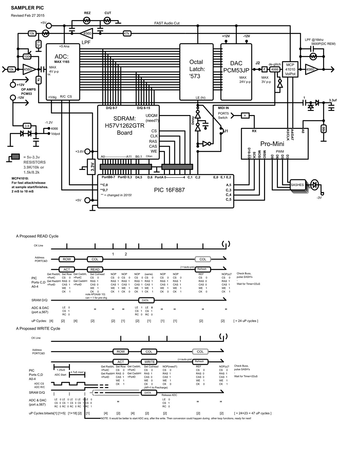
microcontroller, this is it! The diagram says it all....
As mentioned, the PIC16F887 does the "grunt" work of controlling the SDRAM, and the
Arduino does all the fancy stuff. To clarify, the PIC chip controls the
addressing, loading, and transfer of data to and from the SDRAM, ADC,
Latches, and DAC. Not shown it also will control De-glitching of the DAC
output if needed.
Apart from receiving "orders" from the Arduino, this is all the PIC will
do.
The
Arduino will:
-RX Commands from the Main Control (ATMEGA) and run sequences.
-Keep track of raw addressing pointers, or retrieve address data from
PIC
-Send Address data to PIC
-Perhaps control 4 SASH (Sample And Sorta Hold) circuits to control
audio |
 |
|
I have
created a simulation in MPASM for the PIC running at 20 MHz and it seems
to be able to keep up with the sample rate. Originally (Pre-Arduino) I
was using the interrupt routine for MIDI input, and decoding all that
data was a pain, but with SPI the speeds are much better and it can be
raw data which can be interpreted faster. So the interrupt (which is
about 22 cycles, or 4.4uS, won't much interfere with the 15uS (@64Ks/s)
or 20uS (@48Ks/s) sample time. If it's out by a few microseconds in the
end, it's not an issue.
These SDRAM's
are similar to the old DRAM's in that they have equiv. CAS and RAS
address lines, but the sequence of multiple CLK pulses, WE, CAS, RAS, &
CS make for a fairly complex series of events. Throw in the latch LE,
de-glitch, ADC's start acquisition, and CS, things become somewhat
complex. To further explain the Row Refresh I intend on using, which I'm
sure will work fine, here's a table.. |
|
The normal direction for loading/saving to RAM is ROW1--->ROW512, then
refresh next row and pre-charge it to place the entire row onto the
buffers. This allows for multiple sequential reads and writes, with
appropriate clock (2/3) before.
As my
method/application only needs 1 byte at a time, and re-loading the RAS
address, (which will also set up the SDRAM for a refresh), the Sample PIC will step
through ROW's (4096) then increment COL's. Each time the RAS is stepped
into, the refresh cycle will happen, after proper clocks. |
|
ROW1-COL1 |
ROW1-COL2 |
ROW1-COL3 |
ROW1-COL4 |
ROW1-COL5 |
. . . . . . . . .
|
ROW1-COL512 |
|
ROW2-COL1 |
ROW2-COL2 |
ROW2-COL3 |
ROW2-COL4 |
ROW2-COL5 |
. . . . . . . . . |
ROW2-COL512 |
|
ROW3-COL1 |
ROW3-COL2 |
ROW3-COL3 |
ROW3-COL4 |
ROW3-COL5 |
. . . . . . . . . |
ROW3-COL512 |
|
ROW4-COL1 |
ROW4-COL2 |
ROW4-COL3 |
ROW4-COL4 |
ROW4-COL5 |
. . . . . . . . . |
ROW4-COL512 |
|
I see no
reason why this wouldn't work, it'd better!
Since purchasing the SDRAM
board, I have found several of these "H57V" type chips on assorted
boards in my junk boxes, but none of them are 4096 refresh cycles, they
are all 8192 (Same refresh time - 64mS) . This would put the kybosh on
using it for this as that would require a sample rate of 128Ks/s !
Presently, I am
trying to design with a board stacking in mind, to keep it compact. So
once that is figured out, work can begin! |

|
Update April 27th 2015
I found a
PIC18F4220 in my box of PIC microcontrollers, and wow it can go fast! I
can double the clock frequency internally, which makes 40 MHz! This made
a great improvement and allowed for simultaneous Record/Play, which is
really needed for layering.
As can
be seen above, there are 3 main boards, but these sandwich another board
that I found on EBay, the SDRAM breakout. Because of double headers it
was a bit cumbersome, but the boards came out good enough that it wasn't
an issue.
The most
recent schematic I have is the one to the right, (click to see much
larger!) which is pretty accurate except the LPF has been replaced by a
TDA7718 audio processor. It's basically a 3 band EQ designed for car
audio, but has 6 "speaker" outputs and is controlled via I2C like all
TDA's.
For a
while I thought this would defeat the purpose of the MCP41010 digital
Pot, but as it turned out it was needed as well. There was also no need
to "deglitch" the DAC output.
The TDA chip provides the delicate balance of feedback required much
better than SASH circuits did. |
 |
|
Another change
I made was to go to stereo output. It's not true stereo, but when you
hear it, you'll beg to differ. The original signal leaves on the left
side (after passing through the EQ) and the DAC on the left. The DAC can
also occupy both channels and using the EQ then output levels as a
balance can be put anywhere in the soundscape. |
|
I've used 4560 Op Amps, which are surprisingly low with noise, but a
LM833 dual op-amp was added directly to the ADC input (no gain,
4.5nV/√Hz)
and wow what an improvement. 16 bit ADC's don't like much resistance on
their inputs! In the schematic of the mod I have 4560, that's wrong.
In the schematic
above, you can see the diodes feeding the arduino's A0 analog input.
This is for Peak Slicing, one of the 3 types of slicers. It has a
drop-off of about 100mS (depending on where the peak level is set) and
worked much better than I thought. It not only slices at a voltage
crossing, but recognizes a drop, then rise as another slice. So if
there's a cymbal trailing and a hat occurs, the hat will be
registered as a new slice. Nice!
The circuit has of
course been changed. An Op-AMp has been added to give 5:1 gain before
feeding into the cap and diodes. |
 |
I've dubbed the
sampler/looper the "Borg Cube" as with 6 layers, or levels, and it's
seeming complexity, it was the logical name. ( If you're a trekkie like
me! )
So what if there's a few headers on it! The photo below shows the
audio section with the new Mod, the TDA board, which was one of the 2
extras from the main mixer section I had left over.
Also, if
you look at the pics closely, you can see an Arduino Pro-Mini in there
somewhere (behind the crystal in the pic bottom right) It's soldered
right on instead of mounted on a header. I just put a 1K resistor on the
FTDI programmer interface's TxD line so I would'nt fry the tiny FTDI
chip with MIDI data! |
 |
When
apart, photo left, you can see the TDA board stacked on top of the audio
board. It was amazing how all of the wires leading from it lined up! to
access under the board, only the 2 ground wires needs be removed, then
the board will "hinge" on the wires upward and to the left.
A 9 Volt zener limits the
voltage to the TDA which can only accept 10 V maximum. The voltage comes
from the 12 Volts mains.
The analog and
digital grounds have been joined together and the noise reciprocated by
dropping to virtually nothing. |
 |
The
PIC 18F4220 (photo left) has the same footprint as the PIC16F887, so the
board didn't need any changes. This board also houses the MAX1165 16 Bit
ADC, and on the other side, the Arduino Pro-Mini.
The small board above
the ADC was an add-on super low noise Op-Amp to remove any stray noise
between the audio board and the ADC input. It is recommended in the
datasheet.
I used the LM833, which is very low noise (
4.5nV/√Hz
), but hasn't the big price tag.
The board below,
left, is the DAC out board, which uses a PCM 53JP 16 bit DAC. These DACs
were purchased from China on Ebay, fairly cheap, but I suspect the
design is decades old. It has all of the earmarks of the 80's, i.e.
reversed MSB/LSB (Q0 is MSB), big power draw, case style, no input gate
or latch, a "de-glitching" circuit in the datasheet.
It works will,
but is a power pig. The SIAB now has 2 of these, which draw a total of
140mA. That's quite a bit, and they warm up to prove the point! Oh well.
The other 2 chips are
74HCT573 8 bit latches. This load the data from the SDRAM's 16 bit data
bus at the appropriate time. The HCT types seem to work well will 3.3V
logic inputs.
The white box is a multi-turn trim pot that centers the ADC voltage at
1/2 of 4.096V. Because it is capacitively coupled, the input to the ADC
may drift off and a sudden record cycle after sitting quiet can cause a
"pop" at the start, which can be annoying if looping or echoing!
The photo, lower
right, shows a side view of how the boards all fit together. Count them,
6 layers in all. Pretty cool! |
 |
 |
|
So there it is, one really
cool sampler. If I had to do this again, I'd probably go with a
larger processor (ARM) but just had to prove to that guy in whatever
forum it was who said "It can't be done" that yes indeed it can be done!
One Arduino + 1 PIC chip. Granted, the PIC would've been sufficient, but
what about all the toys and additions!
Using The Sampler:

Each part of the
SIAB project has been incredibly fun to build, then use, but the Sampler
has been the best so far. I'm not familiar with hardware sampler/looper's
in general, so am not sure if the features I've added are standard or
bizarre or what, but if you're building a sampler, this may give you
some ideas. Here's the modes it has:
1) Note
Sampler
The Note Sampler is basically like the old "Emulator" in that keys can
be programmed with a sound, which can then be played with other keys.
Refer to the keyboard diag. above.
2) Layer-Loop Tempo
The Layer-Loop Tempo is one of the main features of the Sampler. This
Mode allows controlled looping in layers. That is a tempo-synced loop
can be initiated from a foot switch, or via
MIDI,
then "record paused" to continue looping until the next part is added.
At that point, another tap anywhere in the loop will commence a new
recording at the loop point set by the 2nd tap on the footswitch.
3)
Layer-Loop Free
Sometimes, just a vocal or guitar loop is needed without a tempo, or
more importantly as a part of a band, where tapping is king! A tempo
signal doesn't need to be, or have been, present. This means no
preparation and the only job at hand being tap accuracy. Other than
that, the operation is as with the Layer-Loop Tempo.
IIntroduction
for all Slicers:
The Slicers allow a recorded sample to be divided in 3 different ways,
then assigned to notes in sequence (Notes 72-104, see above diagram) to
be played in a new way! The slices don't loop individually but follow
through as the original recording. This is more intuitive as the
original recording may contain a sound immediately after that wouldn't
sound good by itself. There can be a maximum of 32 slices.
* The Played Notes of the sliced sample are velocity sensitive only if
the velocity is below half (64) at which point the level of sound falls
toward zero. It can never be 0 though or will be interpreted as a note
off. Playing slices by hand usually yields velocities of over 64 so this
isn't an issue, but in a sequencer, there is some control over sample
levels.
4) Tempo Slicer
To record, simply press the Record or Footswitch to begin, then again
to end. If there is a tempo active, (MIDI or internal blue light
flashing) the record will "wait" for the next bar. This is 99% the way
it will be used, so it's automatic. The sample will be sliced according
to the Tempo Sync Setting (1/32,1/24,1/16,1/12,1/8,1/4 etc)
5) Peak Slicer
The Peak slicer is the trickiest of the three slicers. Record
procedure is the same as all slicers, but slices are created from
audio levels rising above the level of Peak (CC#82)
This Mode can be great for acquiring slices of drums or other percussive
sounds, but can work well with voice, and even guitar if the notes are
"plucky". For DJ'ing, from canned music, it can add an element of
randomness which is really fun to play with.
6) Divide Slicer
The Divide Slicer does what it's called, Divides the Recording into
slices. The number of slices can be selected using the Sync setting's
alternate values (32,24,16,8,6,4,3,2,1)
This must be set before the record is commenced, even though the slicing
happens after the Record stop tap. This mode is very useful for
sampling/slicing canned music by pressing the footswitch on the down
beat, then on another downbeat for a predictable slice size and
position.
7) Echo Looper
The Echo Looper is the most "hands-off" Mode. Apart from requiring a
start from the foot switch (Record), and extremely long period, it
resembles a standard echo.
This echo requires a tempo to be present as echoing this long would be
useless otherwise. You'd never know when the wrap around will be. As
with all modes, this mode can be automated or manually controlled. The
echo time can be very short (<1/4 note or a few mS if set that way)
or very long, up to 184 seconds. The echo stop command includes a nice
fade out.
A tempo isn't required but if a song was playing since this mode selected,
that tempo will be used for start synchronization. (Good for trailing
echoes after a song stop)
8) Echo Free
The Echo Free is similar to the Echo Looper, but can be started any
time, whether
MIDI
is playing or not, and, of course, will not be on-sync. The echo time in
fact is controlled by:
Granulizer Size (CC#85) - This is the course tune, 1 mS to .5
seconds
Granulizer Speed (CC#86) - This is the fine tune, mostly for 1,2,3
mS setting on course.
The tighter settings can create a cool flange effect, or a ringing effect
if the EQ is balanced properly. This mode is a good way to test EQ
dynamics affect on longer echoes or for layering as it will show the
changes quickly. If, for example, you wanted the "older" layers to sound
tinnier and distant, set the EQ here then move to the Layer Mode.
9) Foot Hold
The foot hold is very simple compared to other Modes. It is always
recording, so when the footswitch is pressed, it'll hold the last
recorded space that the granulizer Slice is set to.
This is great for holding a vocal note, or guitar note. releasing the
footswitch causes the level to fade down, pressing again halts the fade
and holds at new level.
10) Extras Option
Modes 10-16 have been left open, but
included in the selector for future mode ideas that may become obvious.
FX Modifiers:
1) Pitch Notes
These notes will shift the sample
rate of the sample presently playing or recording. The diagram above
shows the range and notes (+/- 1 octave)
2) Pitch Shifter &
Pitch Wheel
The Pitch Wheel (on most keyboards) will
overtake the Pitch Notes or Dashboard Panel Pitch setting
3) Stutter
Sampler
Effects Old school! The stutter control is really simple. You set the
Adj.(CC104) to a value and this value is AND'ed to the address values
(on play side only) to the SDRAM which creates a stutter or buzz effect.
The stutter setting determines what binary value is AND'ed.
4) Reverser
Reverses the presently playing
sample for time the note is held. Great for seguaying into a different
part of a song. I used during an Echo Mode, Echo is cancelled.
5) Granulizer
A standard granualizer with controls
for progression (forward/reverse) speed and grain size. When activated,
starts looping a small section of the sample playing, but slowly moving
so the loops change giving a "slo-mo" effect. LFO can act on this
creating some excellent FX.
6) LFO
The LFO controls the sample rate with various envelopes from wave shapes
and stepping. The envelopes are sine, triangle, ramp up, ramp down, PWM
up, PWM down, Random (stepped with limits), and Audio Level (the
envelope is actually the level of audio input)
The pitch
Shifter (notes) will work with most of the above, but should only be
used with note sampler and Slices during playback for "non-space alien
effects" operation lol!
The LFO
will work with most of the modes above, but will also record while LFO
varies the sample rate. The LFO has several envelopes, some specialized
for sampling.
This is a really basic look at the Modes and FX. For a more in-depth
look, download the
user manual
(it's in .rtf but MS Office stuff will open it like a .doc)
Here it is in
the long-awaited PDF format
|
| |
Having Fun!! MP3's of various
tests etc.
Here's some audio samples or the ..er sampler! None of these
have been post-processed, just straight off the mixer, recorded live.
Oh and sorry about the no-so-great gitter playing.
Electric guitar is a different world for sure.
EchoFun
This is a sample of using the sampler as a straight echo. The EQ was set
pretty much flat, and the feedback low.
I just love doing this with vocals, although it's kinda freaky
harmonizing with oneself! |
Flange Ring
This sample is of
me playing guitar with Echo Free mode set very tight and then the EQ set
to verge of feedback with midrange Q tight. An eerie sound indeed! |
Layer Free
This sample is
using the Layer Free Mode (no tempo) to layer loops. Notice the hat
sound? That's me pressing on the footswitch to control
addition/subtraction of layers.
Both Guitar and vocals have been sampled in, and the feedback is less
than balanced so each layer fades the last. |
EchoLooper
Tempo
Using a tempo locked echo has it's rewards, and can offer a pretty
relaxing (and addictive!) cycle of chord changes. Blending into the echo
well is the trick. Feedback is set fairly high, but with flat response
on EQ Bass-Midrange. Treble is up a bit to create a "cleaner" sound. |
Live Granualizing
During a layer
loop I decided to start hitting the granualizer "note". It's set at a
pretty large grain.
This didn't affect
the next layer recording. |
Layer Tempo
As above I'm
manually controlling layers being added to the loop with a footswitch.
This sample shows how easy it is to create a song and perform it. Loops
tend to be "chanty" all the same, and I kinda messed up the loop stop,
but nice! |
Slicer Notes
This is a demo of slicing my voice and then playing it back with a
sequencer (the slice record is also in the sequence before this!) It's
pretty standard, but nice to have in a MIDI song, sets it apart from the
rest. |
Live DJ Sequencing
This is just an
example, not even synced with the Bangra playing, and using sequences
that were used to test various FX during development. Stutter, pitch
shift, and reverse can be heard during the mash-up.
Here's even
Better (M.I.A.) |
Layer Tempo
EQ
This sample shows
the EQ bass being removed and how that affects the next layer recorded.
It's kinda dragged out but was still experimental at that time. |
Peak Slicer
As above, a MIDI Sequencer is controlling the record area (me singing)
then playing back a preset bunch of samples. After playing for a bit, it
loops & does it again. (Whistling) This would be really fun to do with
kids! |
Peak Slicing Drums
I recorded to peak slicer the cheapo drums on my Kawai keyboard then
started the sequencer (that has various sample sequences for whatever I
was doing before!) to test the Peak timing. The timing is adjustable as
is the sensitivity.
Notice the tempo and velocity changes? |
Divider Slicer
The sequencer was stopped and I sampled my firewood song playing, then
added those vocals back into the mix by playing the keyboard notes for
those samples. The song is then paused while I do my groove. Beaucoup de
fun!
In a sequence this'd be more predictable for performing. |
| |
Green
Light=Play
/ Red light=Record
I recorded these (rather crap) vocals to demonstrate the capacity to
add, then remove vocal tracks using only the foot switch. You can hear
the screw-up, then it's gone like magic! The lyrics are from looking at
the R/G/Y status indicator. See I'll sing about anything haha! |
|
Regrets:
In a way I wish the sampler stage had been stereo, but that means 1/2 the
recording time, more components, compromised sample rate etc. The output
appears to be in stereo if you listen to the samples above. This is because
of the EQ dynamics, and feeding more of the DAC to one side than another via
the TDA chip.
The original reason for building this for the SIAB project was to just
get a long clean live echo, controllable by the sequencer, primarily for
vocals, that could turn on and off and be in perfect sync. SO, all in all
everything else is bonus!
I hope this page
has given someone some ideas on building that "perfect" sampler! Here's some
code and files..if you can decipher them!
FILES: MPASM PIC
HEX and ASM:SamplePIC.rar,
Arduino SDSsamplePIC.ino,
FL6+ Dashboard artwork
SDSsampler.rar, FL6+ Dashboard Presets
SDSsamplerDash.rar
Completed April
27th 2015
Page updated June 4th 2015
|
Update:
It has been a month or so and I have discovered that samplers are in
demand in the modular synth world, and there is (at least some) interest
in my design.
So, I am considering modifying the Sampler above into a CV/Trigger
controllable sampler module. The hardest part of this for me is not
dreaming up functions and features, but how to fit it all into a modular
panel of reasonable size, and make it look good! Euro seems the best way
to go with the 3.5mm (as opposed to 1/4") jacks, and more compact form
factor.
The next
decision will be whether or not it should be a DIY kit. As shown above,
some of the TSOP stuff is basically outside of the soldering abilities
of the average hobbyist. So those chips would need to be either already
on the boards or on break-out boards up to DIP size.
It's all
up in the air right now, but it would be an interesting challenge to
take up once the SIAB project is complete. Until then, if you're a
modular freak or Muff Wiggler, these samps I've dug up may describe a
small section of the sampler's capabilities. |
Vox Twister
The sample is my voice, sliced into little chunks on-the-fly, then
sequenced as notes. A sequencer could also send CV/triggers to play a
section of divided sample, or a variable position until the next
trigger, which would yield similar results. Reverse play could also be
accomplished this way (via CV<0V or <set V) |
Sliced Up Live
Here's couple a MIDI note (or CV/trig) controlled live recorded samples.
16 chunks are recorded, then played via sequencer. The Kick drum was to
show sync with tempo, clock. The guitar slide at the beginning was
played with that tempo, so it all lines up nicely! So any sound can be
introduced, then sequenced on command. |
GrainFX
This is a layer loop with the playback being granulized mid-way. The
"Hold" function can also do this, but remains on the sample without
moving, whereas granulizing can move around while looping. |
| |
|
|
UPDATE: Aug 29th
2015 I
am presently working with another designer to make the SDS Sampler a Modular
Synth component! (We'll think of a better name!)
Here's a link to the first forum topic in
Muff Wiggler .
I think this will become something amazing! |