 |
|
|
ACCORD R.U.L.E
How to use and Methods
This page will give you some information on using the RULE and how truly flexible it is!
Here are listed tutorials to better help you understand the setup and creating of lines that will make your own Rules for your own system. First I will cover the basics of the Rule Blocks, then how to include a built-in generator or two with your composition to open up a full expanse of possibilities.
 |
The Basics
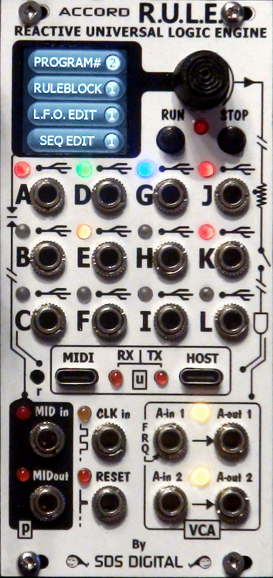
The 12 jacks, A-L, are bidirectional until defined by a line in a Rule
Block. To create lines, click on the [RULEBLOCK] QB (Quick-Box) button,
select (1) for the first Block, and click again to enter the Rules Editor.
If the Block is empty, all you will see is the "EXIT" selection to save work
and exit back to the QB buttons. Scroll the encoder left to make sure the arrow is at the top. This is
where the first line of your Rule will be. Now the Block has one line: OUTD=CV.A Any CV input plugged into jack A will be duplicated at jack D. This isn't very useful, well, unless you have a weak CV force that you need to boost the current to drive a module. With this same line, an octave boost, a negative inversion, a signal multiplier, or divider etc. can be done by extending it a little. Lets say you want to add/subtract two CV's together for, perhaps combining two LFO's. This is simple to do with this one line: 1 - Click on the line to edit it. The first line will now be
OUTD=CV.A+CV.G With
CV's into A and G this is a basic adder, i.e. A=2 volts and G=1 volt means B
will have 3 volts. As all jacks are bipolar, putting 2 volts into A but -2
volts into G will output 0 volts on D. To create a "mixer" scenario instead,
change the "+" to " This is just one line. With more lines much more refined Rules can be created. |
||||||
|
Using Variables To act as intermediaries between inputs and outputs, the
value or state must be held in a holding cell. These "cells" are called
variables. They are a representation of the value you pushed into them. In
the previous examples, the values are mathematically processed then shot
toward the output immediately. With variables, these results can be held,
processed, then released to the output further along in your Rule or in the
Block(s). The first line can be made to send the CV.A+CV.G
information to a variable instead of directly to the OUTD. So the line will now be
VAR1=CV.A+CV.G Now,
what can we do with VAR1? We could use it to set a built in LFO, or ENVelope,
or perhaps quantize it? OK, let's do that! Now VAR2 will hold a value that is quantized to the
nearest lower Volt like 1 octave, i.e. 1.5 volts = 1 volts, 3.5 volts = 3
volts. You could add a third line "OUTD=VAR2"
to verify. Inserting A Line Now is a good time to mention how to insert a line. It's
simple. The RUN and STOP buttons, when in the Block editor, are used to show
the line numbers, and to toggle insert.
Using Conditional Statements (IF, ELSE): There may be a requirement to switch something from one process, or Rule, to another. Lets say for example, you have an old school Sequencer's CV out feeding CV.A of the above example to quantize notes but want to slew some of the notes. The Sequencer outputs a CV to the Slew module on certain steps, but the quantizer we made does it's job and turns the slew into a steppy glissando. Maybe this isn't desirable, so we can use a conditional statements to bypass the quantization rule altogether. Scroll to the first line and press STOP button to insert
a line. Click on the new space and scroll to "IF>".
Click it and IF will be the highlighted conditional, so just click to use
it. The "ELSE" statement is entirely for this purpose! After
the now 5 lines, click the next empty line, select "IF>" and click. Scroll
to "ELSE" and select. The
RULE will want another condition entry "<?>" but don't select anything,
rather just click on <?> to skip, and scroll off of the line to save it. Now
the lines after ELSE will execute, but only if the IF statement is false. Using ENDIF The eighth line should be "ENDIF". Let me explain. The ENDIF statement closes the open IF so that other lines can follow without becoming part of the condition. If an ENDIF is not placed, all following lines (in this case) would only execute when CV.J is over 2.5 volts. At the end of a Block, all open Conditional statements are closed automatically, so if many line are needed for your rules in this block, then it does save space, but even for visual reference, an ENDIF is a good idea! Using Other Conditional (AND, OR, NOT) While in the conditionals list you may have noticed these. While nesting (IF statements anywhere inside of other IF's) is permitted, AND, OR, or NOT must be used immediately after an IF or after an ELSE only. This is mostly to avoid visual and conceptual confusion, as using these can get quite complex. Even with this syntax enforced, things can get out of hand quickly. Here is an example listing:
Conditional Tips Certain practices with conditionals can be greatly advantageous. Using ELSE statements can be much more compact if you consider the control voltage for example. To the left is a pedantic way to do a CV steering patch, while to the right is a sequential organization. Both will work but the right is more compact:
I hope you have learned a few things with this little tutorial, and that I have conveyed the possibilities of this module being part of your modular tools in the future! I will add to this page as time goes on, stay tuned....
|
|||||||
Contact: freshnel@freshnelly.com
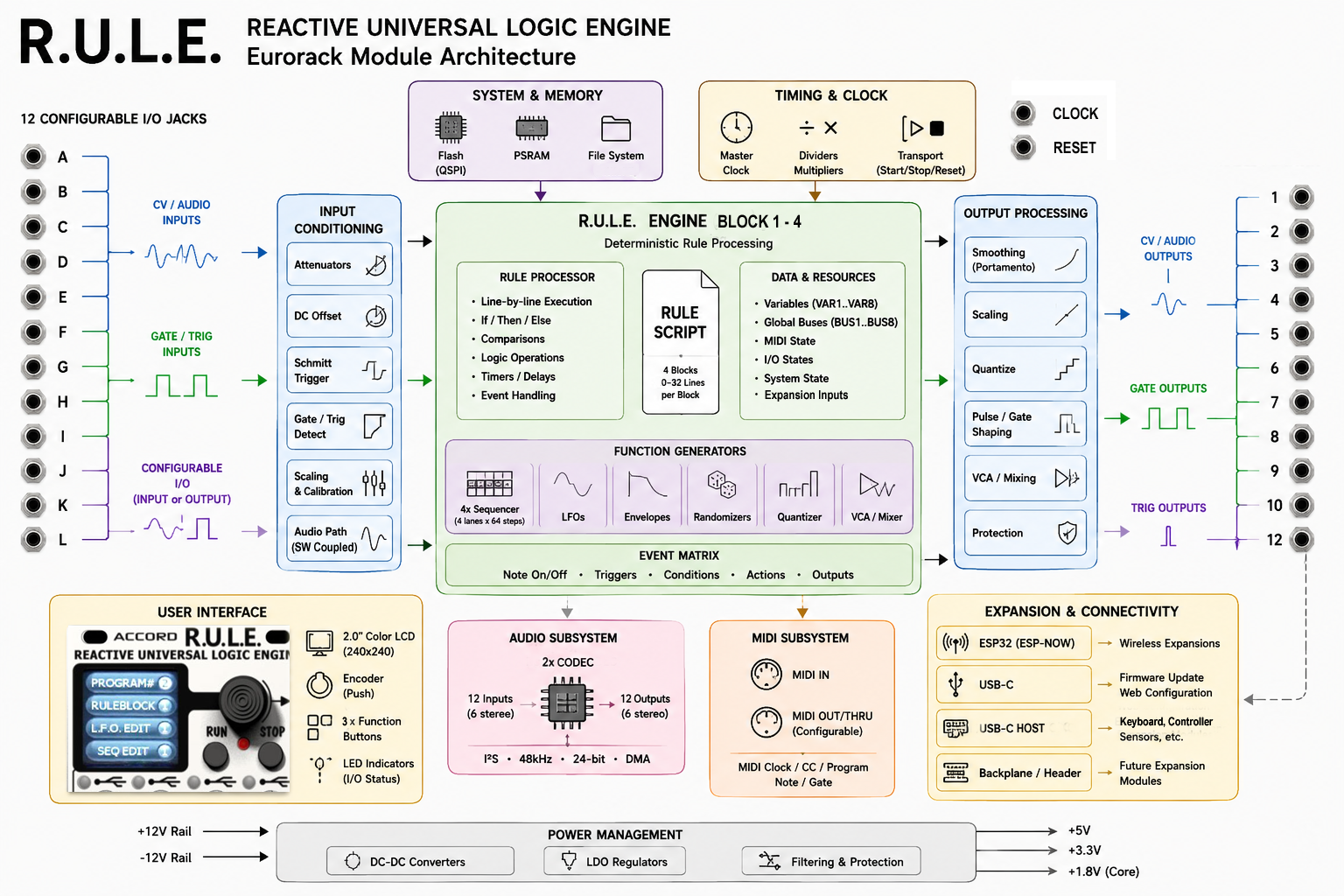
R.U.L.E. Basic Architecture (click to expand)
| This video is creating rules using an HTML page and sending over Wireless directly to the module. |
.gif)

Web Design by Yours Truly! I know it
looks like something out of the 90's when a 1 Mb webpage was unacceptably large.
We strive to separate ourselves from energy consuming bandwidth-heavy script,
AI, and
other wasteful environmental unfriendliness
toward this beautiful blue pearl in space we all call home. I urge you to do the
same please. It feels good!
Last Update July 17th 2026
 " (asterisk). This will require the voltages , or one of
then, be much smaller though. i.e. 3 volts x 3 volts = 9 volts! For a
modular friendly scaled multiply, select the "(x)" operator instead.
" (asterisk). This will require the voltages , or one of
then, be much smaller though. i.e. 3 volts x 3 volts = 9 volts! For a
modular friendly scaled multiply, select the "(x)" operator instead.